ASME B18.2.1 is the American National Standard for Inch Series square, hex, and lobed head bolts and screws. It provides comprehensive dimensional and general data for a wide range of externally driven fasteners, including square, hex, heavy hex, and askew head bolts, as well as lobed head, and lag screws. Use the dimension charts below to find full specifications—including head proportions, body diameters, thread lengths, and tolerances—for product types recognized under this standard.
Dimensions & Size Chart
Hex Bolt Dimensions
Bolt Size
1/4
5/16
3/8
7/16
1/2
5/8
3/4
7/8
1
1-1/8
1-1/4
1-3/8
1-1/2
1-5/8
1-3/4
1-7/8
2
2-1/4
2-1/2
2-3/4
3
3-1/4
3-1/2
3-3/4
4
E
Min
0.237
0.298
0.36
0.421
0.482
0.605
0.729
0.852
0.976
1.098
1.223
1.345
1.47
1.591
1.716
1.839
1.964
2.214
2.461
2.711
2.961
3.21
3.461
3.726
3.975
Max
0.26
0.324
0.388
0.452
0.515
0.642
0.768
0.895
1.022
1.149
1.277
1.404
1.531
1.658
1.785
1.912
2.039
2.305
2.559
2.827
3.081
3.335
3.589
3.858
4.111
F
Min
0.425
0.484
0.544
0.603
0.725
0.906
1.088
1.269
1.45
1.631
1.812
1.994
2.175
2.356
2.538
2.719
2.9
3.262
3.625
3.988
4.35
4.712
5.075
5.437
5.8
Max
0.438
0.5
0.562
0.625
0.75
0.938
1.125
1.312
1.5
1.688
1.875
2.062
2.25
2.438
2.625
2.812
3
3.375
3.75
4.125
4.5
4.875
5.25
5.625
6
G
Min
0.484
0.552
0.62
0.687
0.826
1.033
1.24
1.447
1.653
1.859
2.066
2.273
2.48
2.616
2.893
3.099
3.306
3.719
4.133
4.546
4.959
5.372
5.786
6.198
6.612
Max
0.505
0.577
0.65
0.722
0.866
1.083
1.299
1.516
1.732
1.949
2.165
2.382
2.598
2.815
3.301
3.248
3.464
3.897
4.33
4.763
5.196
5.629
6.062
6.495
6.928
H
Min
0.15
0.195
0.226
0.272
0.302
0.378
0.455
0.531
0.591
0.658
0.749
0.81
0.902
0.978
1.054
1.13
1.175
1.327
1.479
1.632
1.815
1.936
2.057
2.241
2.424
Max
0.188
0.235
0.268
0.316
0.364
0.444
0.524
0.604
0.7
0.78
0.876
0.94
1.036
1.116
1.196
1.276
1.388
1.548
1.708
1.869
2.06
2.251
2.38
2.572
2.764
R
Min
0.01
0.01
0.01
0.01
0.01
0.02
0.02
0.02
0.03
0.03
0.03
0.03
0.03
0.03
0.04
0.04
0.04
0.06
0.06
0.06
0.06
0.06
0.06
0.06
0.06
Max
0.03
0.03
0.03
0.03
0.03
0.06
0.06
0.06
0.09
0.09
0.09
0.09
0.09
0.09
0.12
0.12
0.12
0.19
0.19
0.19
0.19
0.19
0.19
0.19
0.19
LT
L < 6 inch
0.75
0.875
1
1.125
1.25
1.5
1.75
2
2.25
2.5
2.75
3
3.25
3.5
3.75
4
4.25
4.75
5.25
5.75
6.25
6.75
7.25
7.75
8.25
L > 6 inch
1
1.125
1.25
1.375
1.5
1.75
2
2.25
2.5
2.75
3
3.25
3.5
3.75
4
4.25
4.5
5
5.5
6
6.5
7
7.5
8
8.5
Note: All measurements are in inches
Disclaimer: The dimensions presented on this page are based on the applicable industry standard. However, actual product measurements may vary slightly due to manufacturing practices, material selection, surface finish, and specified tolerance classes. Buyers and sourcing professionals are encouraged to verify final specifications with the manufacturer or supplier prior to procurement, particularly for critical applications.
Legend
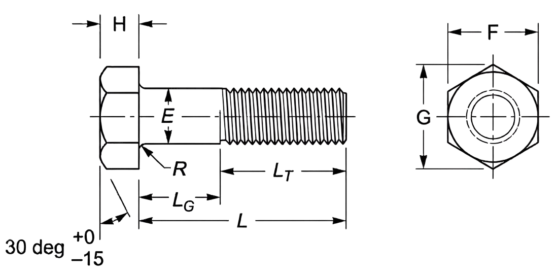
E – Body Diameter: The thickness of the unthreaded shank used to calculate the necessary clearance hole size and determine the bolt’s overall shear strength.
F – Width Across Flats: The distance between two parallel flat surfaces of the bolt head, used to identify the correct wrench or spanner size for installation.
G – Width Across Corners: The maximum diameter of the hexagonal head measured from point to point, ensuring enough clearance for the tool to rotate.
H – Head Height: The vertical thickness of the head, critical for ensuring the bolt does not protrude or interfere with moving components in tight assemblies.
R – Radius of Underhead Fillet: The curved transition where the shank meets the head; it provides essential stress relief to prevent the head from snapping under tension.
LT – Thread Length: The portion of the bolt featuring functional threads, determining the maximum engagement depth into a tapped hole or nut.
L – Nominal Length: The total reach of the fastener from the under-head bearing surface to the tip.
LG – Grip Length: The distance from the head to the first full thread (the unthreaded shear plane).
Technical Note
Maximum Grip Gaging Length (LG, max) = Lnom - LTFor bolts not threaded full length, the maximum grip gaging length is calculated as the nominal bolt length minus the nominal thread length. This value is used as the primary criterion for inspection and determining thread availability.
LG Calculation & Tolerance Example
Bolt Size : 7/16-14 x 4.000 in.
Pitch (P) : 1 ÷ 14 TPI = 0.0714 in
LG (Max) : 4.000 - 1.380 = 2.620 in
Minimum Design Grip Length : 2.620 - (5 x 0.0714) = 2.263 in (Reflects the tolerance of minus five coarse thread pitches)
Length - Standard increments and permissible tolerances based on nominal bolt size and length:
For nominal bolt sizes 1/4 to 1.00 in.:
Up to 1.00 in. lengths: 0.06 to 0.13 in. increments with a tolerance of +0.02 / -0.03.
Over 1.00 through 2.50 in. lengths: 0.25 in. increments with tolerances ranging from +0.02 / -0.04 for smaller diameters to +0.08 / -0.10 for 1.00 in. bolts.
Over 2.50 through 4.00 in. lengths: 0.25 in. increments with tolerances ranging from +0.04 / -0.06 to +0.10 / -0.14.
Over 4.00 through 6.00 in. lengths: 0.50 in. increments with tolerances ranging from +0.06 / -0.10 to +0.12 / -0.16.
Longer than 6.00 in. lengths: 1.00 in. increments with tolerances ranging from +0.10 / -0.18 to +0.16 / -0.20.
For nominal bolt sizes over 1.00 in.:
Over 1.00 through 2.50 in. lengths: 0.50 in. increments with tolerances ranging from +0.12 / -0.12 to +0.18 / -0.18.
Over 2.50 through 4.00 in. lengths: 0.50 in. increments with tolerances ranging from +0.16 / -0.16 to +0.20 / -0.20.
Over 4.00 through 6.00 in. lengths: 0.50 in. increments with tolerances ranging from +0.18 / -0.18 to +0.22 / -0.22.
Longer than 6.00 in. lengths: 1.00 to 2.00 in. increments with tolerances ranging from +0.22 / -0.22 to +0.24 / -0.24.
Heavy Hex Bolt Dimensions
Bolt Size
3/8
1/2
5/8
3/4
7/8
1
1-1/8
1-1/4
1-3/8
1-1/2
1-5/8
1-3/4
1-7/8
2
2-1/4
2-1/2
2-3/4
3
E
Min
0.36
0.482
0.605
0.729
0.852
0.976
1.098
1.223
1.345
1.47
1.591
1.716
1.839
1.964
2.214
2.461
2.711
2.961
Max
0.388
0.515
0.642
0.768
0.895
1.022
1.149
1.277
1.404
1.531
1.658
1.785
1.912
2.039
2.035
2.559
2.827
3.081
F
Min
0.669
0.85
1.031
1.212
1.394
1.575
1.756
1.938
2.119
2.3
2.481
2.662
2.844
3.025
3.388
3.75
4.112
4.475
Max
0.688
0.875
1.062
1.25
1.438
1.625
1.812
2
2.188
2.375
2.562
2.75
2.938
3.125
3.5
3.875
4.25
4.625
G
Min
0.763
0.969
1.175
1.383
1.589
1.796
2.002
2.209
2.416
2.622
2.829
3.035
3.242
3.449
3.862
4.275
4.688
5.102
Max
0.794
1.01
1.227
1.443
1.66
1.876
2.093
2.309
2.526
2.742
2.959
3.175
3.392
3.608
4.041
4.474
4.907
5.34
H
Min
0.226
0.302
0.378
0.455
0.531
0.591
0.658
0.749
0.81
0.902
0.978
1.054
1.13
1.175
1.327
1.479
1.632
1.815
Max
0.268
0.364
0.444
0.524
0.604
0.7
0.78
0.876
0.94
1.036
1.116
1.196
1.276
1.388
1.548
1.708
1.869
2.06
R
Min
0.01
0.01
0.02
0.02
0.02
0.03
0.03
0.03
0.03
0.03
0.03
0.04
0.04
0.04
0.06
0.06
0.06
0.06
Max
0.03
0.03
0.06
0.06
0.06
0.09
0.09
0.09
0.09
0.09
0.09
0.12
0.12
0.12
0.19
0.19
0.19
0.19
LT
L < 6 inch
1
1.25
1.5
1.75
2
2.25
2.5
2.75
3
3.25
3.5
3.75
4
4.25
4.75
5.25
5.75
6.25
L > 6 inch
1.25
1.5
1.75
2
2.25
2.5
2.75
3
3.25
3.5
3.75
4
4.25
4.5
5
5.5
6
6.5
Note: All measurements are in inches
Disclaimer: The dimensions presented on this page are based on the applicable industry standard. However, actual product measurements may vary slightly due to manufacturing practices, material selection, surface finish, and specified tolerance classes. Buyers and sourcing professionals are encouraged to verify final specifications with the manufacturer or supplier prior to procurement, particularly for critical applications.
Legend
E – Body Diameter: The thickness of the unthreaded shank used to calculate the necessary clearance hole size and determine the bolt’s overall shear strength.
F – Width Across Flats: The distance between two parallel flat surfaces of the bolt head, used to identify the correct wrench or spanner size for installation.
G – Width Across Corners: The maximum diameter of the hexagonal head measured from point to point, ensuring enough clearance for the tool to rotate.
H – Head Height: The vertical thickness of the head, critical for ensuring the bolt does not protrude or interfere with moving components in tight assemblies.
R – Radius of Underhead Fillet: The curved transition where the shank meets the head; it provides essential stress relief to prevent the head from snapping under tension.
LT – Thread Length: The portion of the bolt featuring functional threads, determining the maximum engagement depth into a tapped hole or nut.
L – Nominal Length: The total reach of the fastener from the under-head bearing surface to the tip.
LG – Grip Length: The distance from the head to the first full thread (the unthreaded shear plane).
Technical Note
Maximum Grip Gaging Length (LG, max) = Lnom - LTFor bolts not threaded full length, the maximum grip gaging length is calculated as the nominal bolt length minus the nominal thread length. This value is used as the primary criterion for inspection and determining thread availability.
LG Calculation & Tolerance Example
Bolt Size : 7/16-14 x 4.000 in.
Pitch (P) : 1 ÷ 14 TPI = 0.0714 in
LG (Max) : 4.000 - 1.380 = 2.620 in
Minimum Design Grip Length : 2.620 - (5 x 0.0714) = 2.263 in (Reflects the tolerance of minus five coarse thread pitches)
Length - Standard increments and permissible tolerances based on nominal bolt size and length:
For nominal bolt sizes 1/4 to 1.00 in.:
Up to 1.00 in. lengths: 0.06 to 0.13 in. increments with a tolerance of +0.02 / -0.03.
Over 1.00 through 2.50 in. lengths: 0.25 in. increments with tolerances ranging from +0.02 / -0.04 for smaller diameters to +0.08 / -0.10 for 1.00 in. bolts.
Over 2.50 through 4.00 in. lengths: 0.25 in. increments with tolerances ranging from +0.04 / -0.06 to +0.10 / -0.14.
Over 4.00 through 6.00 in. lengths: 0.50 in. increments with tolerances ranging from +0.06 / -0.10 to +0.12 / -0.16.
Longer than 6.00 in. lengths: 1.00 in. increments with tolerances ranging from +0.10 / -0.18 to +0.16 / -0.20.
For nominal bolt sizes over 1.00 in.:
Over 1.00 through 2.50 in. lengths: 0.50 in. increments with tolerances ranging from +0.12 / -0.12 to +0.18 / -0.18.
Over 2.50 through 4.00 in. lengths: 0.50 in. increments with tolerances ranging from +0.16 / -0.16 to +0.20 / -0.20.
Over 4.00 through 6.00 in. lengths: 0.50 in. increments with tolerances ranging from +0.18 / -0.18 to +0.22 / -0.22.
Longer than 6.00 in. lengths: 1.00 to 2.00 in. increments with tolerances ranging from +0.22 / -0.22 to +0.24 / -0.24.
Square Head Bolt Dimensions
Bolt Size
1/4
5/16
3/8
7/16
1/2
5/8
3/4
7/8
1
1-1/8
1-1/4
1-3/8
1-1/2
E
Min
0.237
0.298
0.36
0.421
0.482
0.605
0.729
0.852
0.976
1.098
1.223
1.345
1.47
Max
0.26
0.324
0.388
0.452
0.515
0.642
0.768
0.895
1.022
1.149
1.277
1.404
1.531
F
Min
0.362
0.484
0.544
0.603
0.725
0.906
1.088
1.269
1.45
1.631
1.812
1.994
2.175
Max
0.375
0.5
0.562
0.625
0.75
0.938
1.125
1.312
1.5
1.688
1.875
2.062
2.25
G
Min
0.498
0.665
0.747
0.828
0.995
1.244
1.494
1.742
1.991
2.239
2.489
2.738
2.986
Max
0.53
0.707
0.795
0.884
1.061
1.326
1.591
1.856
2.121
2.386
2.652
2.917
3.182
H
Min
0.156
0.186
0.232
0.278
0.308
0.4
0.476
0.568
0.628
0.72
0.812
0.872
0.964
Max
0.188
0.22
0.268
0.316
0.348
0.444
0.524
0.62
0.684
0.78
0.876
0.94
1.036
R
Min
0.01
0.01
0.01
0.01
0.01
0.02
0.02
0.02
0.03
0.03
0.03
0.03
0.03
Max
0.03
0.03
0.03
0.03
0.03
0.06
0.06
0.06
0.09
0.09
0.09
0.09
0.09
LT
L < 6 inch
0.75
0.875
1
1.125
1.25
1.5
1.75
2
2.25
2.5
2.75
3
3.25
L > 6 inch
1
1.125
1.25
1.375
1.5
1.75
2
2.25
2.5
2.75
3
3.25
3.5
Note: All measurements are in inches
Disclaimer: The dimensions presented on this page are based on the applicable industry standard. However, actual product measurements may vary slightly due to manufacturing practices, material selection, surface finish, and specified tolerance classes. Buyers and sourcing professionals are encouraged to verify final specifications with the manufacturer or supplier prior to procurement, particularly for critical applications.
Legend
E – Body Diameter: The thickness of the unthreaded shank used to calculate the necessary clearance hole size and determine the bolt’s overall shear strength.
F – Width Across Flats: The distance between two parallel flat surfaces of the bolt head, used to identify the correct wrench or spanner size for installation.
G – Width Across Corners: The maximum diameter of the hexagonal head measured from point to point, ensuring enough clearance for the tool to rotate.
H – Head Height: The vertical thickness of the head, critical for ensuring the bolt does not protrude or interfere with moving components in tight assemblies.
R – Radius of Underhead Fillet: The curved transition where the shank meets the head; it provides essential stress relief to prevent the head from snapping under tension.
LT – Thread Length: The portion of the bolt featuring functional threads, determining the maximum engagement depth into a tapped hole or nut.
L – Nominal Length: The total reach of the fastener from the under-head bearing surface to the tip.
LG – Grip Length: The distance from the head to the first full thread (the unthreaded shear plane).
Technical Note
Maximum Grip Gaging Length (LG, max) = Lnom - LTFor bolts not threaded full length, the maximum grip gaging length is calculated as the nominal bolt length minus the nominal thread length. This value is used as the primary criterion for inspection and determining thread availability.
LG Calculation & Tolerance Example
Bolt Size : 7/16-14 x 4.000 in.
Pitch (P) : 1 ÷ 14 TPI = 0.0714 in
LG (Max) : 4.000 - 1.380 = 2.620 in
Minimum Design Grip Length : 2.620 - (5 x 0.0714) = 2.263 in (Reflects the tolerance of minus five coarse thread pitches)
Length - Standard increments and permissible tolerances based on nominal bolt size and length:
For nominal bolt sizes 1/4 to 1.00 in.:
Up to 1.00 in. lengths: 0.06 to 0.13 in. increments with a tolerance of +0.02 / -0.03.
Over 1.00 through 2.50 in. lengths: 0.25 in. increments with tolerances ranging from +0.02 / -0.04 for smaller diameters to +0.08 / -0.10 for 1.00 in. bolts.
Over 2.50 through 4.00 in. lengths: 0.25 in. increments with tolerances ranging from +0.04 / -0.06 to +0.10 / -0.14.
Over 4.00 through 6.00 in. lengths: 0.50 in. increments with tolerances ranging from +0.06 / -0.10 to +0.12 / -0.16.
Longer than 6.00 in. lengths: 1.00 in. increments with tolerances ranging from +0.10 / -0.18 to +0.16 / -0.20.
For nominal bolt sizes over 1.00 in.:
Over 1.00 through 2.50 in. lengths: 0.50 in. increments with tolerances ranging from +0.12 / -0.12 to +0.18 / -0.18.
Over 2.50 through 4.00 in. lengths: 0.50 in. increments with tolerances ranging from +0.16 / -0.16 to +0.20 / -0.20.
Over 4.00 through 6.00 in. lengths: 0.50 in. increments with tolerances ranging from +0.18 / -0.18 to +0.22 / -0.22.
Longer than 6.00 in. lengths: 1.00 to 2.00 in. increments with tolerances ranging from +0.22 / -0.22 to +0.24 / -0.24.
Askew Bolt Dimensions
Bolt Size
3/8
1/2
5/8
3/4
7/8
1
E
Min
0.36
0.482
0.605
0.729
0.852
0.976
Max
0.388
0.515
0.642
0.768
0.895
1.022
F
Min
0.544
0.725
0.906
1.088
1.269
1.45
Max
0.562
0.75
0.938
1.125
1.312
1.5
G
Min
0.747
0.995
1.244
1.494
1.742
1.991
Max
0.795
1.061
1.326
1.591
1.856
2.121
H1
Min
0.277
0.371
0.48
0.574
0.683
0.761
Max
0.317
0.411
0.52
0.614
0.723
0.801
H
Reference
0.25
0.328
0.422
0.5
0.594
0.656
R
Min
0.01
0.01
0.02
0.02
0.02
0.03
Max
0.03
0.03
0.06
0.06
0.06
0.09
S
Max
0.25
0.312
0.344
0.406
0.438
0.5
LT
L < 6 inch
1
1.25
1.5
1.75
2
2.25
L > 6 inch
1.25
1.5
1.75
2
2.25
2.5
Note: All measurements are in inches
Disclaimer: The dimensions presented on this page are based on the applicable industry standard. However, actual product measurements may vary slightly due to manufacturing practices, material selection, surface finish, and specified tolerance classes. Buyers and sourcing professionals are encouraged to verify final specifications with the manufacturer or supplier prior to procurement, particularly for critical applications.
Legend
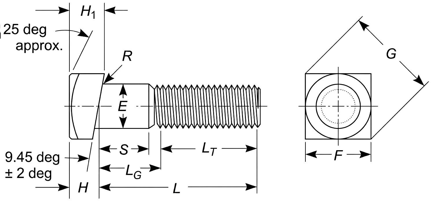
E – Body Diameter: The thickness of the unthreaded shank used to calculate the necessary clearance hole size and determine the bolt’s overall shear strength.
F – Width Across Flats: The distance between two parallel flat surfaces of the bolt head, used to identify the correct wrench or spanner size.
G – Width Across Corners: The maximum diameter of the head measured from point to point, ensuring enough tool clearance.
H1 – Head Height: The maximum vertical thickness of the askew head at its highest point.
H – Mid Height: The height of the bolt head measured specifically at the centerline of the shank.
S – Unthreaded / Shank Length: The portion of the bolt between the under-head bearing surface and the start of the threads.
R – Radius of Underhead Fillet: The curved transition where the shank meets the head; it provides essential stress relief to prevent the head from snapping.
LT – Thread Length: The portion of the bolt featuring functional threads, determining the maximum engagement depth into a tapped hole or nut.
L – Nominal Length: The total reach of the fastener from the under-head bearing surface to the tip.
LG – Grip Length: The distance from the head to the first full thread (the unthreaded shear plane).
Technical Note
Thread Series: These fasteners are exclusively available with Unified Coarse (UNC) threads.
Head Height Geometry: While midheight H follows standard square bolt dimensions, the total head height H1 is calculated as H + 0.0833 times of specified width across flats (F) with a permissible tolerance of 0.020 in.
Maximum Grip Gaging Length (LG, max) = Lnom - LTFor bolts not threaded full length, the maximum grip gaging length is calculated as the nominal bolt length minus the nominal thread length. This value is used as the primary criterion for inspection and determining thread availability.
LG Calculation & Tolerance Example
Bolt Size : 7/16-14 x 4.000 in.
Pitch (P) : 1 ÷ 14 TPI = 0.0714 in
LG (Max) : 4.000 - 1.380 = 2.620 in
Minimum Design Grip Length : 2.620 - (5 x 0.0714) = 2.263 in (Reflects the tolerance of minus five coarse thread pitches)
Length - Standard increments and permissible tolerances based on nominal bolt size and length:
For nominal bolt sizes 1/4 to 1.00 in.:
Up to 1.00 in. lengths: 0.06 to 0.13 in. increments with a tolerance of +0.02 / -0.03.
Over 1.00 through 2.50 in. lengths: 0.25 in. increments with tolerances ranging from +0.02 / -0.04 for smaller diameters to +0.08 / -0.10 for 1.00 in. bolts.
Over 2.50 through 4.00 in. lengths: 0.25 in. increments with tolerances ranging from +0.04 / -0.06 to +0.10 / -0.14.
Over 4.00 through 6.00 in. lengths: 0.50 in. increments with tolerances ranging from +0.06 / -0.10 to +0.12 / -0.16.
Longer than 6.00 in. lengths: 1.00 in. increments with tolerances ranging from +0.10 / -0.18 to +0.16 / -0.20.
For nominal bolt sizes over 1.00 in.:
Over 1.00 through 2.50 in. lengths: 0.50 in. increments with tolerances ranging from +0.12 / -0.12 to +0.18 / -0.18.
Over 2.50 through 4.00 in. lengths: 0.50 in. increments with tolerances ranging from +0.16 / -0.16 to +0.20 / -0.20.
Over 4.00 through 6.00 in. lengths: 0.50 in. increments with tolerances ranging from +0.18 / -0.18 to +0.22 / -0.22.
Longer than 6.00 in. lengths: 1.00 to 2.00 in. increments with tolerances ranging from +0.22 / -0.22 to +0.24 / -0.24.
Hex Flange Bolt Dimensions
Bolt Size
1/4
5/16
3/8
7/16
1/2
9/16
5/8
3/4
E
Min
0.245
0.3065
0.369
0.4305
0.493
0.5545
0.617
0.741
Max
0.25
0.3125
0.375
0.4375
0.5
0.5625
0.625
0.75
F
Min
0.367
0.489
0.551
0.612
0.736
0.798
0.922
1.1
Max
0.375
0.5
0.5625
0.625
0.75
0.8125
0.9375
1.125
G
Min
0.409
0.548
0.618
0.685
0.825
0.895
1.034
1.234
Max
0.433
0.577
0.65
0.722
0.866
0.938
1.083
1.299
H1
Min
0.17
0.21
0.25
0.3
0.34
0.38
0.42
0.51
H
Max
0.28
0.32
0.39
0.46
0.51
0.57
0.62
0.73
B
Max
0.56
0.68
0.81
0.93
1.07
1.19
1.33
1.59
K
Min
0.04
0.05
0.06
0.07
0.08
0.09
0.1
0.11
R2
Max
0.015
0.019
0.022
0.026
0.03
0.034
0.038
0.045
B1
Min
0.48
0.6
0.73
0.85
0.98
1.1
1.23
1.47
LT
L < 6 inch
0.75
0.875
1
1.125
1.25
1.375
1.5
1.75
L > 6 inch
1
1.125
1.25
1.375
1.5
1.625
1.75
2
Note: All measurements are in inches
Disclaimer: The dimensions presented on this page are based on the applicable industry standard. However, actual product measurements may vary slightly due to manufacturing practices, material selection, surface finish, and specified tolerance classes. Buyers and sourcing professionals are encouraged to verify final specifications with the manufacturer or supplier prior to procurement, particularly for critical applications.
Legend
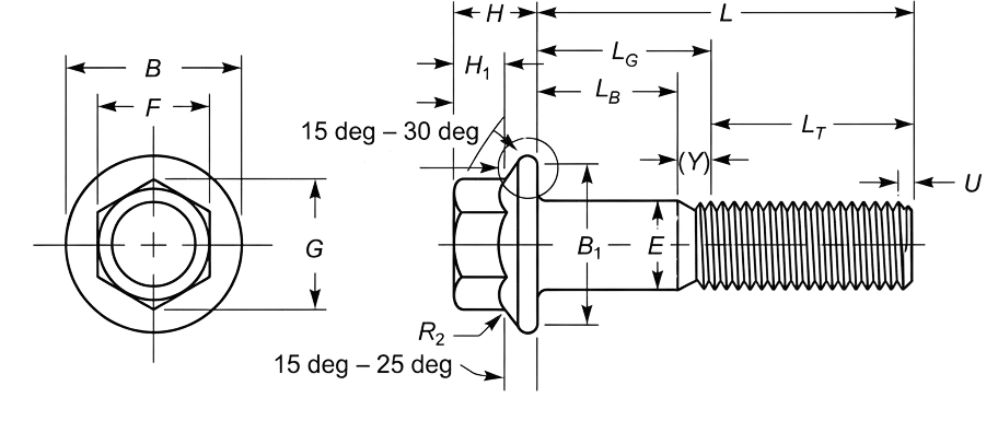
E – Body Diameter: The thickness of the unthreaded shank used to calculate the necessary clearance hole size and determine the bolt’s overall shear strength.
F – Width Across Flats: The distance between two parallel flat surfaces of the hexagonal head, used to identify the correct wrench or spanner size.
G – Width Across Corners: The maximum diameter of the hexagonal head measured from point to point, ensuring enough clearance for the tool to rotate.
H1 – Hex Height: The height of the hexagonal portion of the bolt head, excluding the flange thickness.
H – Head Height: The total vertical thickness of the head, measured from the bearing surface to the top of the bolt.
B – Flange Diameter: The maximum outer diameter of the integral flange (the built-in washer) at its widest point.
K – Flange Thickness: The thickness of the flange section at its outer rim.
R2 – Top Flange Radius: The radius of the curved transition where the hexagonal flats meet the top surface of the flange.
B1 – Bearing Diameter: The diameter of the effective flat contact area on the underside of the flange.
LT – Thread Length: The portion of the bolt featuring functional threads, determining the maximum engagement depth into a tapped hole or nut.
L – Nominal Length: The total reach of the fastener from the under-head bearing surface to the tip.
LG – Grip Length: The distance from the head to the first full thread (the unthreaded shear plane).
Technical Note
Maximum Grip Gaging Length (LG, max) = Lnom - LTFor bolts not threaded full length, the maximum grip gaging length is calculated as the nominal bolt length minus the nominal thread length. This value is used as the primary criterion for inspection and determining thread availability.
LG Calculation & Tolerance Example
Bolt Size : 7/16-14 x 4.000 in.
Pitch (P) : 1 ÷ 14 TPI = 0.0714 in
LG (Max) : 4.000 - 1.380 = 2.620 in
Minimum Design Grip Length : 2.620 - (5 x 0.0714) = 2.263 in (Reflects the tolerance of minus five coarse thread pitches)
Length - Standard increments and permissible tolerances based on nominal bolt size and length:
For nominal bolt sizes 1/4 to 1.00 in.:
Up to 1.00 in. lengths: 0.06 to 0.13 in. increments with a tolerance of +0.02 / -0.03.
Over 1.00 through 2.50 in. lengths: 0.25 in. increments with tolerances ranging from +0.02 / -0.04 for smaller diameters to +0.08 / -0.10 for 1.00 in. bolts.
Over 2.50 through 4.00 in. lengths: 0.25 in. increments with tolerances ranging from +0.04 / -0.06 to +0.10 / -0.14.
Over 4.00 through 6.00 in. lengths: 0.50 in. increments with tolerances ranging from +0.06 / -0.10 to +0.12 / -0.16.
Longer than 6.00 in. lengths: 1.00 in. increments with tolerances ranging from +0.10 / -0.18 to +0.16 / -0.20.
For nominal bolt sizes over 1.00 in.:
Over 1.00 through 2.50 in. lengths: 0.50 in. increments with tolerances ranging from +0.12 / -0.12 to +0.18 / -0.18.
Over 2.50 through 4.00 in. lengths: 0.50 in. increments with tolerances ranging from +0.16 / -0.16 to +0.20 / -0.20.
Over 4.00 through 6.00 in. lengths: 0.50 in. increments with tolerances ranging from +0.18 / -0.18 to +0.22 / -0.22.
Longer than 6.00 in. lengths: 1.00 to 2.00 in. increments with tolerances ranging from +0.22 / -0.22 to +0.24 / -0.24.
Hex Cap Screw Dimensions
Bolt Size
1/4
5/16
3/8
7/16
1/2
9/16
5/8
3/4
7/8
1
1-1/8
1-1/4
1-3/8
1-1/2
1-5/8
1-3/4
1-7/8
2
2-1/4
2-1/2
2-3/4
3
E
Min
0.245
0.3065
0.369
0.4305
0.493
0.5545
0.617
0.741
0.866
0.99
1.114
1.239
1.363
1.488
1.613
1.738
1.863
1.988
2.238
2.488
2.738
2.988
Max
0.25
0.3125
0.375
0.4375
0.5
0.5625
0.625
0.75
0.875
1
1.125
1.25
1.375
1.5
1.625
1.75
1.875
2
2.25
2.5
2.75
3
F
Min
0.428
0.489
0.551
0.612
0.736
0.798
0.922
1.1
1.285
1.469
1.631
1.812
1.994
2.175
2.356
2.538
2.719
2.9
3.262
3.625
3.988
4.35
Max
0.438
0.5
0.562
0.625
0.75
0.812
0.938
1.125
1.312
1.5
1.688
1.875
2.062
2.25
2.438
2.625
2.812
3
3.375
3.75
4.125
4.5
G
Min
0.488
0.557
0.628
0.698
0.84
0.91
1.051
1.254
1.465
1.675
1.859
2.066
2.273
2.48
2.686
2.893
3.099
3.306
3.719
4.133
4.546
4.959
Max
0.505
0.577
0.65
0.722
0.866
0.938
1.083
1.299
1.516
1.732
1.949
2.165
2.382
2.598
2.815
3.031
3.248
3.464
3.897
4.33
4.763
5.196
H
Min
0.15
0.195
0.226
0.272
0.302
0.348
0.378
0.455
0.531
0.591
0.658
0.749
0.81
0.902
0.962
1.054
1.114
1.175
1.327
1.479
1.632
1.815
Max
0.163
0.211
0.243
0.291
0.323
0.371
0.403
0.483
0.563
0.627
0.718
0.813
0.878
0.974
1.038
1.134
1.198
1.263
1.423
1.583
1.744
1.935
LT
L < 6 inch
0.75
0.875
1
1.125
1.25
1.375
1.5
1.75
2
2.25
2.5
2.75
3
3.25
3.5
3.75
4
4.25
—
—
—
—
L > 6 inch
1
1.125
1.25
1.375
1.5
1.625
1.75
2
2.25
2.5
2.75
3
3.25
3.5
3.75
4
4.25
4.5
5
5.5
6
6.5
Note: All measurements are in inches
Disclaimer: The dimensions presented on this page are based on the applicable industry standard. However, actual product measurements may vary slightly due to manufacturing practices, material selection, surface finish, and specified tolerance classes. Buyers and sourcing professionals are encouraged to verify final specifications with the manufacturer or supplier prior to procurement, particularly for critical applications.
Legend
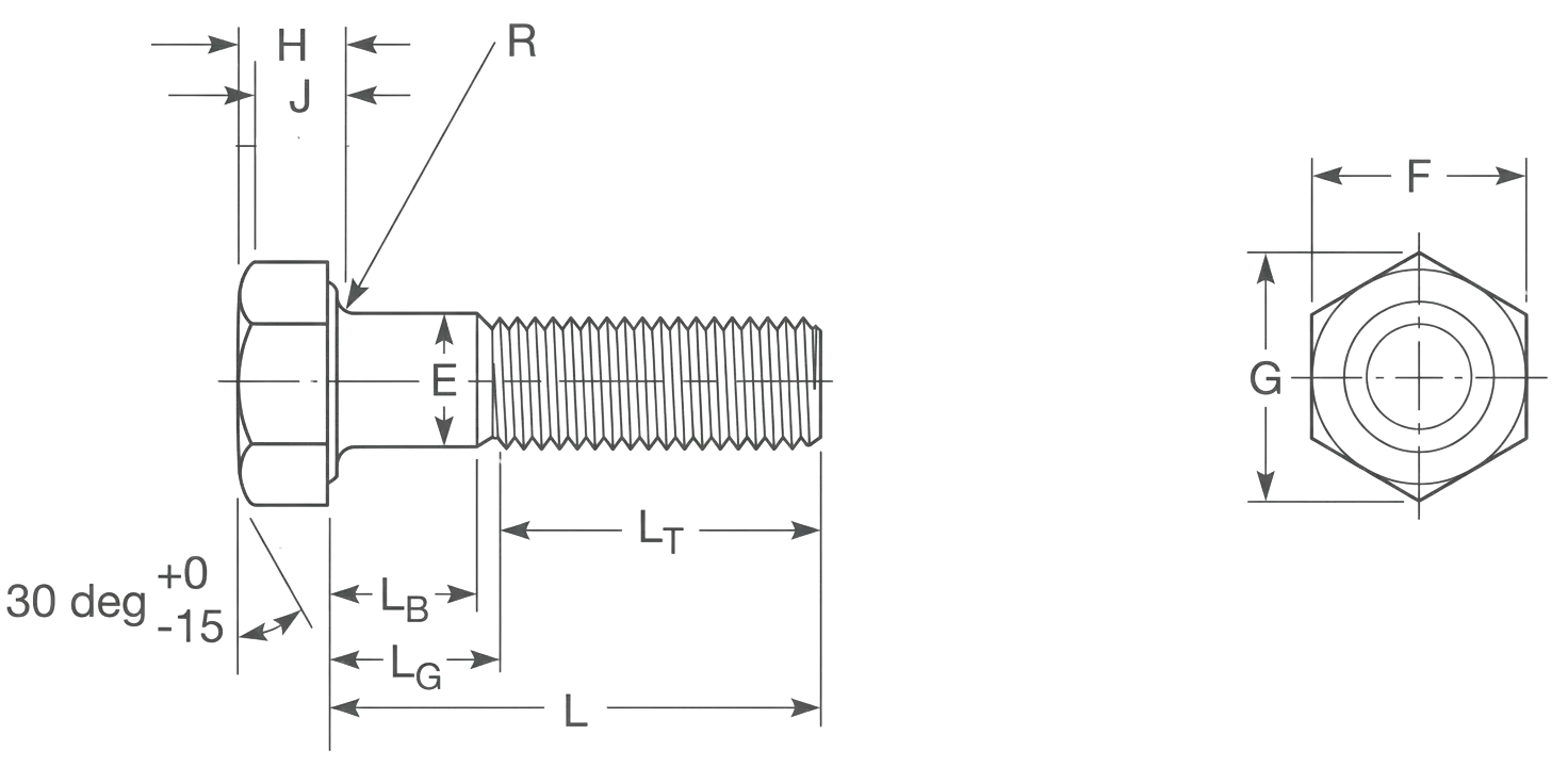
A – Head Diameter: The maximum width of the bolt head, which dictates the required size of a counterbore hole so the fastener can sit flush or recessed within a surface.
D – Body Diameter: The thickness of the unthreaded shank used to calculate the necessary clearance hole size and determine the bolt’s overall shear strength.
H – Head Height: The vertical thickness of the head, a critical measurement for ensuring the bolt does not protrude or interfere with other moving components in tight assemblies.
J – Hexagon Socket Size: The distance across the internal flats of the drive, which identifies the specific hex key or Allen wrench size needed for installation.
T – Socket Depth: The vertical engagement depth for the drive tool, ensuring there is enough surface area to transfer full torque without stripping the internal socket.
G – Minimum Wall Thickness: The metal remaining between the socket and the outer head edge, which provides the structural integrity needed to prevent the head from cracking under high tension.
L – Nominal Length: The total reach of the fastener from the under-head bearing surface to the tip, used as the primary identifier for ordering and specifying joint depth.
LG – Grip Length: The distance from the head to the first full thread, ensuring that the stronger, unthreaded portion of the bolt is positioned where the joined materials meet (the shear plane).
LB – Body Length: The unthreaded portion of the shank that provides a smooth, precise bearing surface for parts that must align or pivot without thread interference.
LT – Thread Length: The portion of the bolt featuring functional threads, which determines the maximum engagement depth into a tapped hole or nut to ensure a secure hold.
K – Edge of Head: The perimeter of the bolt head which determines the minimum clearance required within a counterbore and provides the structural boundary for the bearing surface.
F – Underhead Fillet: The curved radius where the shank meets the head, which provides essential stress relief to prevent the head from snapping off under heavy tension.
C – Top Head Chamfer: The beveled top edge of the head that removes sharp corners for user safety and helps guide tools into the socket more efficiently.
Technical Note
Grip Gaging Length (LG) = Lnom - LT(min)Calculated by subtracting the minimum thread length from the nominal length. It defines the maximum distance from the bearing surface to the first complete thread.
Body Length (LB) = LG - (5 x P)
Calculated by subtracting five thread pitches (P) from the Grip Gaging Length. This defines the minimum length of the perfectly smooth, unthreaded shank by accounting for thread runout.
LG & LB Calculation Example
Screw Size : 7/16-14 x 4.000 in.
Pitch (P) : 1 ÷ 14 TPI = 0.0714 in
LG : 4.000 - 1.380 = 2.620 in
LB : 2.620 - (5 x 0.0714) = 2.263 in
Length - Standard length and it's increments that are determined by the nominal screw size and length:
For nominal screw sizes 0 to 1.00 in :
0.13 through 0.25 in. lengths: 0.06 in. increments
0.25 through 1.00 in. lengths: 0.13 in. increments
1.00 through 3.50 in. lengths: 0.25 in. increments
3.50 through 7.00 in. lengths: 0.50 in. increments
7.00 through 10.00 in. lengths: 1.00 in. increments
For nominal screw sizes over 1.00 in.:
1.00 through 7.00 in. lengths: 0.50 in. increments
7.00 through 10.00 in. lengths: 1.00 in. increments
Over 10.00 in. lengths: 2.00 in. increments
Hex Lag Screw Dimensions
Screw Size
#10
1/4
5/16
3/8
7/16
1/2
5/8
3/4
7/8
1
1-1/8
1-1/4
E
Min
0.178
0.237
0.298
0.36
0.421
0.482
0.605
0.729
0.852
0.976
1.098
1.223
Max
0.199
0.26
0.324
0.388
0.452
0.515
0.642
0.768
0.895
1.022
1.149
1.277
F
Min
0.271
0.362
0.484
0.544
0.603
0.725
0.906
1.088
1.269
1.45
1.631
1.812
Max
0.281
0.375
0.5
0.562
0.625
0.75
0.938
1.125
1.312
1.5
1.688
1.875
G
Min
0.309
0.484
0.552
0.62
0.687
0.826
1.033
1.24
1.447
1.653
1.859
2.066
Max
0.323
0.505
0.577
0.65
0.722
0.866
1.083
1.299
1.516
1.732
1.949
2.165
H
Min
0.11
0.15
0.195
0.226
0.272
0.302
0.378
0.455
0.531
0.591
0.658
0.749
Max
0.14
0.188
0.235
0.268
0.316
0.364
0.444
0.524
0.604
0.7
0.78
0.876
S
Min
0.094
0.094
0.125
0.128
0.156
0.156
0.312
0.375
0.375
0.625
0.625
0.625
R
Min
0.01
0.01
0.01
0.01
0.01
0.01
0.02
0.02
0.02
0.03
0.03
0.03
Max
0.03
0.03
0.03
0.03
0.03
0.03
0.06
0.06
0.06
0.09
0.09
0.09
Note: All measurements are in inches
Disclaimer: The dimensions presented on this page are based on the applicable industry standard. However, actual product measurements may vary slightly due to manufacturing practices, material selection, surface finish, and specified tolerance classes. Buyers and sourcing professionals are encouraged to verify final specifications with the manufacturer or supplier prior to procurement, particularly for critical applications.
Legend
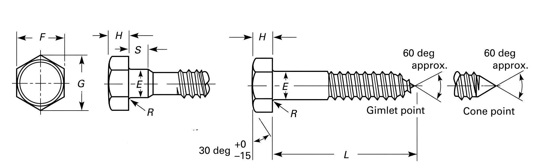
E – Body or Shoulder Diameter: The diameter of the unthreaded shank, used to determine the correct clearance hole size and pilot hole for the threads.
F – Width Across Flats: The distance between parallel sides of the hexagonal head, which identifies the specific wrench or socket size required for installation.
G – Width Across Corners: The maximum width of the hexagonal head measured point-to-point, critical for ensuring socket clearance in recessed spaces.
H – Head Height: The vertical thickness of the hex head, used to calculate the depth of a counterbore or to ensure no interference with moving parts.
S – Shoulder Length: The length of the unthreaded portion of the shank, providing a smooth bearing surface and increasing shear resistance in the primary material.
R – Radius of Underhead Fillet: The curved transition between the shank and the head that provides stress relief to prevent head-snapping under high torque.
L – Nominal Length: The total length of the screw measured from the under-head bearing surface to the extreme tip.
Technical Note
Thread Length (LT) – Standard requirements for thread coverage:
General Formula: The standard minimum thread length is calculated as half of the nominal screw length plus 0.50 inches.
Maximum Requirement: The documentation caps this minimum at 6 inches; if the formula results in a larger number, 6 inches is used as the minimum.
Short Fasteners: For screws too short to meet the formula, the standard requires them to be threaded as close to the head or shoulder as possible.
Length Tolerances – The allowable deviation from the nominal length (+0.00 for all) based on screw size and length:
For nominal screw sizes 1/4 to 3/4 in:
Up to 1.00 in. lengths: -0.03 in. tolerance
Over 1.00 through 2.50 in. lengths: -0.04 to -0.08 in. tolerance
Over 2.50 through 4.00 in. lengths: -0.06 to -0.10 in. tolerance
Over 4.00 through 6.00 in. lengths: -0.10 in. tolerance
Longer than 6.00 in. lengths: -0.18 in. tolerance
For nominal screw sizes 7/8 to over 1-1/2 in:
Over 1.00 through 2.50 in. lengths: -0.10 to -0.18 in. tolerance
Over 2.50 through 4.00 in. lengths: -0.14 to -0.20 in. tolerance
Over 4.00 through 6.00 in. lengths: -0.16 to -0.22 in. tolerance
Longer than 6.00 in. lengths: -0.20 to -0.24 in. tolerance
Square Lag Screw Dimensions
Screw Size
#10
1/4
5/16
3/8
7/16
1/2
5/8
3/4
7/8
1
1-1/8
1-1/4
E
Min
0.178
0.237
0.298
0.36
0.421
0.482
0.605
0.729
0.852
0.976
1.098
1.223
Max
0.199
0.26
0.324
0.388
0.452
0.515
0.642
0.768
0.895
1.022
1.149
1.277
F
Min
0.271
0.362
0.484
0.544
0.603
0.725
0.906
1.088
1.269
1.45
1.631
1.812
Max
0.281
0.375
0.5
0.562
0.625
0.75
0.938
1.125
1.312
1.5
1.688
1.875
G
Min
0.372
0.498
0.665
0.747
0.828
0.995
1.244
1.494
1.742
1.991
2.239
2.489
Max
0.398
0.53
0.707
0.795
0.884
1.061
1.326
1.591
1.856
2.121
2.386
2.652
H
Min
0.11
0.156
0.186
0.232
0.278
0.308
0.4
0.476
0.568
0.628
0.72
0.812
Max
0.14
0.188
0.22
0.268
0.316
0.348
0.444
0.524
0.62
0.684
0.78
0.876
S
Min
0.094
0.094
0.125
0.125
0.156
0.156
0.312
0.375
0.375
0.625
0.625
0.625
R
Min
0.01
0.01
0.01
0.01
0.01
0.01
0.02
0.02
0.02
0.03
0.03
0.03
Max
0.03
0.03
0.03
0.03
0.03
0.03
0.06
0.06
0.06
0.09
0.09
0.09
Note: All measurements are in inches
Disclaimer: The dimensions presented on this page are based on the applicable industry standard. However, actual product measurements may vary slightly due to manufacturing practices, material selection, surface finish, and specified tolerance classes. Buyers and sourcing professionals are encouraged to verify final specifications with the manufacturer or supplier prior to procurement, particularly for critical applications.
Legend
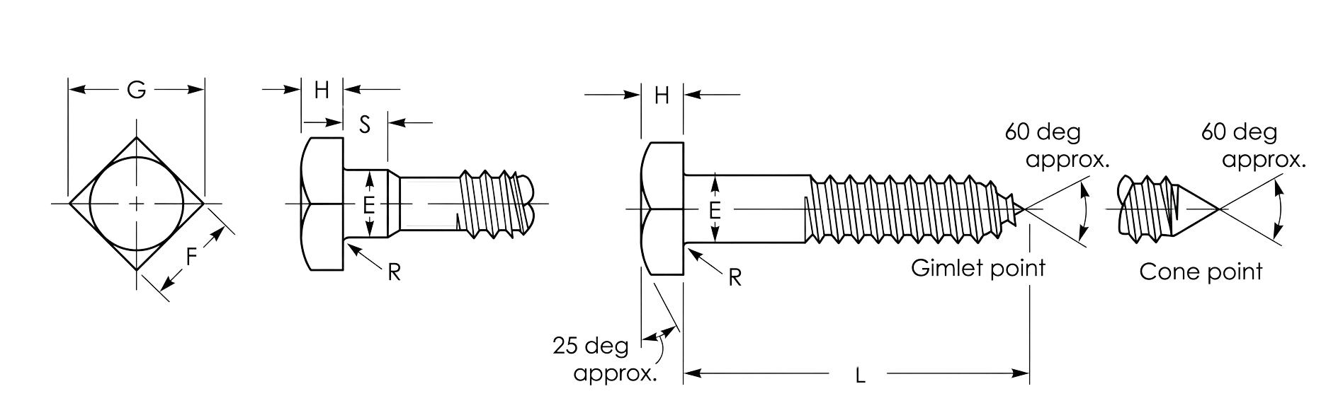
E – Body or Shoulder Diameter: The diameter of the unthreaded shank, used to determine the correct clearance hole size and pilot hole for the threads.
F – Width Across Flats: The distance between parallel sides of the hexagonal head, which identifies the specific wrench or socket size required for installation.
G – Width Across Corners: The maximum width of the hexagonal head measured point-to-point, critical for ensuring socket clearance in recessed spaces.
H – Head Height: The vertical thickness of the hex head, used to calculate the depth of a counterbore or to ensure no interference with moving parts.
S – Shoulder Length: The length of the unthreaded portion of the shank, providing a smooth bearing surface and increasing shear resistance in the primary material.
R – Radius of Underhead Fillet: The curved transition between the shank and the head that provides stress relief to prevent head-snapping under high torque.
L – Nominal Length: The total length of the screw measured from the under-head bearing surface to the extreme tip.
Technical Note
Thread Length (LT) – Standard requirements for thread coverage:
General Formula: The standard minimum thread length is calculated as half of the nominal screw length plus 0.50 inches.
Maximum Requirement: The documentation caps this minimum at 6 inches; if the formula results in a larger number, 6 inches is used as the minimum.
Short Fasteners: For screws too short to meet the formula, the standard requires them to be threaded as close to the head or shoulder as possible.
Length Tolerances – The allowable deviation from the nominal length (+0.00 for all) based on screw size and length:
For nominal screw sizes 1/4 to 3/4 in:
Up to 1.00 in. lengths: -0.03 in. tolerance
Over 1.00 through 2.50 in. lengths: -0.04 to -0.08 in. tolerance
Over 2.50 through 4.00 in. lengths: -0.06 to -0.10 in. tolerance
Over 4.00 through 6.00 in. lengths: -0.10 in. tolerance
Longer than 6.00 in. lengths: -0.18 in. tolerance
For nominal screw sizes 7/8 to over 1-1/2 in:
Over 1.00 through 2.50 in. lengths: -0.10 to -0.18 in. tolerance
Over 2.50 through 4.00 in. lengths: -0.14 to -0.20 in. tolerance
Over 4.00 through 6.00 in. lengths: -0.16 to -0.22 in. tolerance
Longer than 6.00 in. lengths: -0.20 to -0.24 in. tolerance