ASME B18.2.2 is the American National Standard for Inch Series nuts designed for general applications. It provides comprehensive dimensional and general data for a wide range of internally threaded fasteners, including machine screw nuts (regular and small pattern), hex flange nuts, coupling nuts, and various configurations of square, hex, and heavy hex nuts—including flat, jam, slotted, and thick styles. Use the dimension charts below to find full specifications, including width across flats, nut thickness, and slot gaging requirements, for all product types recognized under this standard.
Dimensions & Size Chart
Hex & Jam Nut Dimensions
Nut Size
#0
#1
#2
#3
#4
#5
#6
#8
#10
#12
1/4
5/16
3/8
7/16
1/2
9/16
5/8
3/4
7/8
1
1-1/8
1-1/4
1-3/8
1-1/2
1-5/8
1-3/4
1-7/8
2
2-1/4
2-1/2
2-3/4
3
3-1/4
3-1/2
3-3/4
4
F
Min
0.15
0.15
0.18
0.18
0.241
0.302
0.302
0.332
0.362
0.423
0.428
0.489
0.551
0.675
0.736
0.861
0.922
1.088
1.269
1.45
1.631
1.812
1.994
2.175
2.35
2.538
2.722
2.9
3.263
3.625
3.988
4.35
4.713
5.075
5.438
5.8
Max
0.156
0.156
0.188
0.188
0.25
0.312
0.312
0.344
0.375
0.438
0.438
0.5
0.563
0.688
0.75
0.875
0.938
1.125
1.312
1.5
1.688
1.875
2.062
2.25
2.43
2.625
2.813
3
3.375
3.75
4.125
4.5
4.875
5.25
5.625
6
G
Min
0.171
0.171
0.205
0.205
0.275
0.344
0.344
0.378
0.413
0.482
0.488
0.557
0.628
0.768
0.84
0.982
1.051
1.24
1.447
1.653
1.859
2.066
2.273
2.48
2.679
2.893
3.103
3.306
3.719
4.133
4.546
4.959
5.373
5.786
6.199
6.612
Max
0.18
0.18
0.217
0.217
0.289
0.361
0.361
0.397
0.433
0.505
0.505
0.577
0.65
0.794
0.866
1.01
1.083
1.299
1.516
1.732
1.949
2.165
2.382
2.598
2.805
3.031
3.247
3.464
3.897
4.33
4.763
5.196
5.629
6.062
6.495
6.928
H
Min
0.043
0.043
0.057
0.057
0.087
0.102
0.102
0.117
0.117
0.148
0.212
0.258
0.32
0.365
0.427
0.473
0.535
0.617
0.724
0.831
0.939
1.03
1.138
1.245
1.364
1.46
1.567
1.675
1.89
2.105
2.319
2.534
2.749
2.964
3.178
3.393
Max
0.05
0.05
0.066
0.066
0.098
0.114
0.114
0.13
0.13
0.161
0.226
0.273
0.337
0.385
0.448
0.496
0.559
0.665
0.776
0.887
0.999
1.094
1.206
1.317
1.416
1.54
1.651
1.763
1.986
2.209
2.431
2.654
2.877
3.1
3.322
3.545
H1
Min
—
—
—
—
—
—
—
—
—
—
0.15
0.18
0.21
0.24
0.302
0.301
0.363
0.398
0.458
0.519
0.579
0.687
0.747
0.808
0.868
0.929
0.989
1.05
1.155
1.401
1.522
1.643
1.748
1.87
1.99
2.112
Max
—
—
—
—
—
—
—
—
—
—
0.163
0.195
0.227
0.26
0.323
0.324
0.387
0.446
0.51
0.575
0.639
0.751
0.815
0.88
0.944
1.009
1.073
1.138
1.267
1.427
1.556
1.685
1.814
1.943
2.072
2.201
Note: All measurements are in inches
Disclaimer: The dimensions presented on this page are based on the applicable industry standard. However, actual product measurements may vary slightly due to manufacturing practices, material selection, surface finish, and specified tolerance classes. Buyers and sourcing professionals are encouraged to verify final specifications with the manufacturer or supplier prior to procurement, particularly for critical applications.
Legend
F – Width Across Flats: The distance between two parallel flat surfaces of the nut, used to identify the correct wrench or socket size for installation.
G – Width Across Corners: The maximum diameter of the nut measured from point to point, ensuring enough clearance for the tool to rotate within an assembly.
H – Hex Nut Thickness / Height: The total vertical thickness of a standard hex nut, providing the necessary thread engagement to meet its proof load rating.
H1 – Jam Nut Thickness / Height: The thickness of the thinner "jam" nut, typically used to lock a standard nut in place or in applications where space is too restricted for a full-height nut.
Heavy Hex & Heavy Jam Nut Dimensions
Nut Size
1/4
5/16
3/8
7/16
1/2
9/16
5/8
3/4
7/8
1
1-1/8
1-1/4
1-3/8
1-1/2
1-5/8
1-3/4
1-7/8
2
2-1/4
2-1/2
2-3/4
3
3-1/4
3-1/2
3-3/4
4
F
Min
0.488
0.546
0.669
0.728
0.85
0.909
1.031
1.212
1.394
1.575
1.756
1.938
2.119
2.3
2.481
2.662
2.844
3.025
3.388
3.75
4.112
4.475
4.838
5.2
5.562
5.925
Max
0.5
0.562
0.688
0.75
0.875
0.938
1.062
1.25
1.438
1.625
1.812
2
2.188
2.375
2.562
2.75
2.938
3.125
3.5
3.875
4.25
4.625
5
5.375
5.75
6.125
G
Min
0.556
0.622
0.763
0.83
0.969
1.037
1.175
1.382
1.589
1.796
2.002
2.209
2.416
2.622
2.828
3.035
3.242
3.449
3.862
4.275
4.688
5.102
5.515
5.928
6.341
6.755
Max
0.577
0.65
0.794
0.866
1.01
1.083
1.227
1.443
1.66
1.876
2.093
2.309
2.526
2.742
2.959
3.175
3.392
3.608
4.041
4.474
4.907
5.34
5.774
6.207
6.64
7.073
H
Min
0.218
0.28
0.341
0.403
0.464
0.526
0.587
0.71
0.833
0.956
1.079
1.187
1.31
1.433
1.556
1.679
1.802
1.925
2.155
2.401
2.647
2.893
3.124
3.37
3.616
3.862
Max
0.25
0.314
0.377
0.441
0.504
0.568
0.631
0.758
0.885
1.012
1.139
1.251
1.378
1.505
1.632
1.759
1.886
2.013
2.251
2.505
2.759
3.031
3.252
3.506
3.706
4.014
H1
Min
0.156
0.186
0.216
0.247
0.277
0.307
0.337
0.398
0.458
0.519
0.579
0.687
0.747
0.808
0.868
0.929
0.989
1.05
1.155
1.401
1.522
1.643
1.748
1.87
1.99
2.112
Max
0.188
0.22
0.252
0.285
0.317
0.349
0.381
0.446
0.51
0.575
0.639
0.751
0.815
0.88
0.944
1.009
1.073
1.138
1.251
1.505
1.634
1.763
1.876
2.006
2.134
2.264
Note: All measurements are in inches
Disclaimer: The dimensions presented on this page are based on the applicable industry standard. However, actual product measurements may vary slightly due to manufacturing practices, material selection, surface finish, and specified tolerance classes. Buyers and sourcing professionals are encouraged to verify final specifications with the manufacturer or supplier prior to procurement, particularly for critical applications.
Legend
F – Width Across Flats: The distance between two parallel flat surfaces of the nut, used to identify the correct wrench or socket size for installation.
G – Width Across Corners: The maximum diameter of the nut measured from point to point, ensuring enough clearance for the tool to rotate within an assembly.
H – Heavy Hex Nut Thickness / Height: The total vertical thickness of a standard heavy hex nut, providing the necessary thread engagement to meet its proof load rating.
H1 – Heavy Jam Nut Thickness / Height: The thickness of the thinner "jam" nut, typically used to lock a standard nut in place or in applications where space is too restricted for a full-height nut.
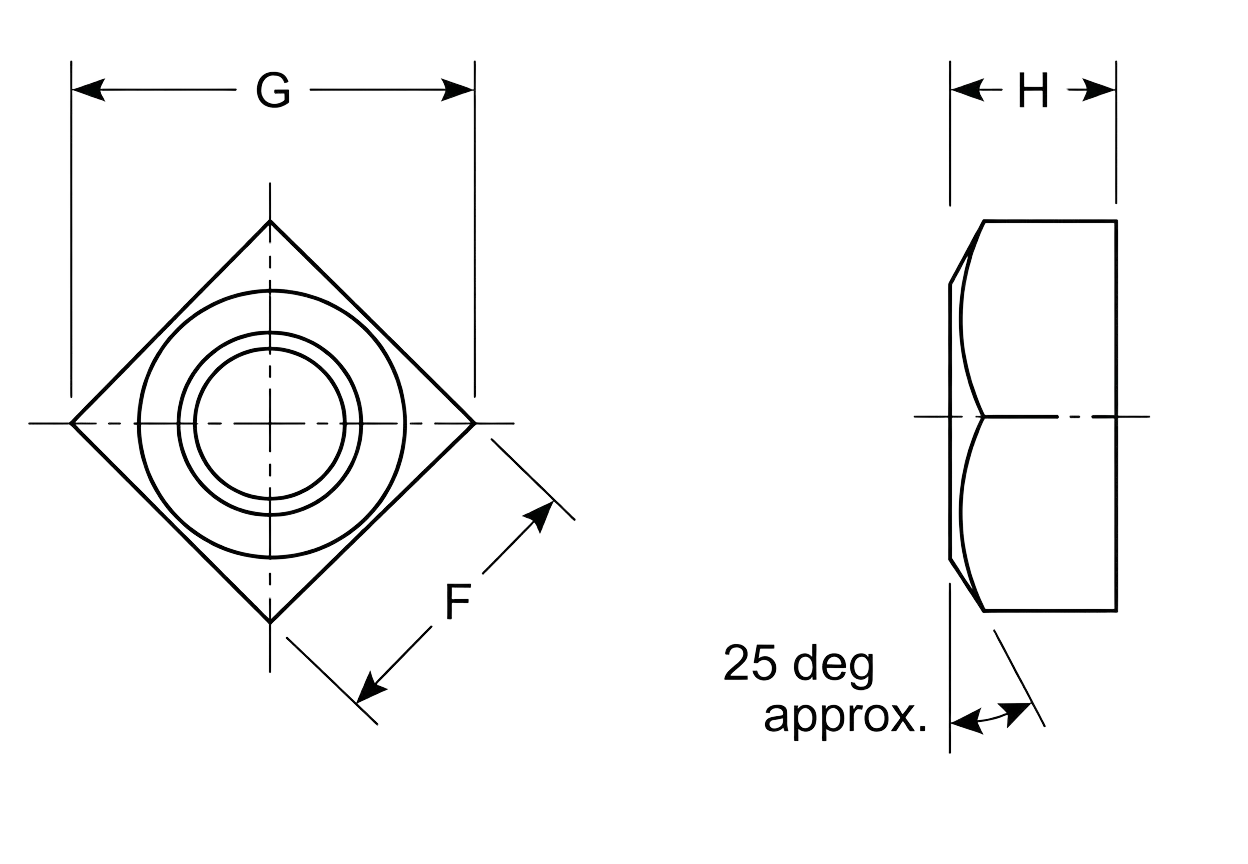
Square Nut Dimensions
Nut Size
#0
#1
#2
#3
#4
#5
#6
#8
#10
#12
1/4
5/16
3/8
7/16
1/2
5/8
3/4
7/8
1
1-1/8
1-1/4
1-3/8
1-1/2
F
Nominal
5/32
5/32
3/16
3/16
1/4
5/16
5/16
11/32
3/8
7/16
7/16
9/16
5/8
3/4
13/16
1
1-1/8
1-5/16
1-1/2
1-11/16
1-7/8
2-1/16
2-1/4
Min
0.15
0.15
0.18
0.18
0.241
0.302
0.302
0.332
0.362
0.423
0.425
0.547
0.606
0.728
0.788
0.969
1.088
1.269
1.45
1.631
1.812
1.994
2.175
Max
0.156
0.156
0.188
0.188
0.25
0.312
0.312
0.344
0.375
0.438
0.438
0.562
0.625
0.75
0.812
1
1.125
1.312
1.5
1.688
1.875
2.062
2.25
G
Min
0.206
0.206
0.247
0.247
0.331
0.415
0.415
0.456
0.497
0.581
0.554
0.721
0.802
0.97
1.052
1.3
1.464
1.712
1.961
2.209
2.458
2.708
2.956
Max
0.221
0.221
0.265
0.265
0.354
0.442
0.442
0.486
0.53
0.619
0.619
0.795
0.884
1.061
1.149
1.414
1.591
1.856
2.121
2.386
2.652
2.917
3.182
H
Min
0.043
0.043
0.057
0.057
0.087
0.102
0.102
0.117
0.117
0.148
0.203
0.249
0.31
0.356
0.418
0.525
0.632
0.74
0.847
0.97
1.062
1.169
1.276
Max
0.05
0.05
0.066
0.066
0.098
0.114
0.114
0.13
0.13
0.161
0.235
0.283
0.346
0.394
0.458
0.569
0.68
0.792
0.903
1.03
1.126
1.237
1.348
Note: All measurements are in inches
Disclaimer: The dimensions presented on this page are based on the applicable industry standard. However, actual product measurements may vary slightly due to manufacturing practices, material selection, surface finish, and specified tolerance classes. Buyers and sourcing professionals are encouraged to verify final specifications with the manufacturer or supplier prior to procurement, particularly for critical applications.
Legend
F – Width Across Flats: The distance between two parallel flat surfaces of the nut, used to identify the correct wrench or socket size for installation.
G – Width Across Corners: The maximum diameter of the nut measured from point to point, ensuring enough clearance for the tool to rotate within an assembly.
H – Thickness / Height: The total vertical thickness of a nut, providing the necessary thread engagement to meet its proof load rating.
Heavy Square Nut Dimensions
Nut Size
1/4
5/16
3/8
7/16
1/2
5/8
3/4
7/8
1
1-1/8
1-1/4
1-3/8
1-1/2
F
Nominal
1/2
9/16
11/16
3/4
7/8
1-1/16
1-1/4
1-7/16
1-5/8
1-13/16
2
2-3/16
2-3/8
Min
0.488
0.546
0.669
0.728
0.85
1.031
1.212
1.394
1.575
1.756
1.938
2.119
2.3
Max
0.5
0.562
0.688
0.75
0.875
1.062
1.25
1.438
1.625
1.812
2
2.188
2.375
G
Min
0.64
0.72
0.889
0.97
1.137
1.386
1.635
1.884
2.132
2.381
2.631
2.879
3.128
Max
0.707
0.795
0.973
1.06
1.237
1.503
1.768
2.033
2.298
2.563
2.828
3.094
3.359
H
Min
0.218
0.28
0.341
0.403
0.464
0.587
0.71
0.833
0.956
1.079
1.187
1.31
1.433
Max
0.266
0.33
0.393
0.456
0.52
0.647
0.774
0.901
1.028
1.155
1.282
1.409
1.536
Note: All measurements are in inches
Disclaimer: The dimensions presented on this page are based on the applicable industry standard. However, actual product measurements may vary slightly due to manufacturing practices, material selection, surface finish, and specified tolerance classes. Buyers and sourcing professionals are encouraged to verify final specifications with the manufacturer or supplier prior to procurement, particularly for critical applications.
Legend
F – Width Across Flats: The distance between two parallel flat surfaces of the nut, used to identify the correct wrench or socket size for installation.
G – Width Across Corners: The maximum diameter of the nut measured from point to point, ensuring enough clearance for the tool to rotate within an assembly.
H – Thickness / Height: The total vertical thickness of a nut, providing the necessary thread engagement to meet its proof load rating.
Castle Nut Dimensions
Nut Size
1/4
5/16
3/8
7/16
1/2
9/16
5/8
3/4
7/8
1
1-1/8
1-1/4
1-3/8
1-1/2
F
Min
0.428
0.489
0.551
0.675
0.736
0.861
0.922
1.088
1.269
1.45
1.631
1.812
1.994
2.175
Max
0.438
0.5
0.562
0.688
0.75
0.875
0.938
1.125
1.312
1.5
1.688
1.875
2.062
2.25
G
Min
0.488
0.557
0.628
0.768
0.84
0.982
1.051
1.24
1.447
1.653
1.859
2.066
2.273
2.48
Max
0.505
0.577
0.65
0.794
0.866
1.01
1.083
1.299
1.516
1.732
1.949
2.165
2.382
2.598
H
Min
0.212
0.258
0.32
0.365
0.427
0.473
0.535
0.617
0.724
0.831
0.939
1.03
1.138
1.245
Max
0.226
0.273
0.337
0.385
0.448
0.496
0.559
0.665
0.776
0.887
0.999
1.094
1.206
1.317
T
Min
0.12
0.16
0.19
0.21
0.27
0.29
0.32
0.38
0.49
0.56
0.61
0.67
0.78
0.82
Max
0.14
0.18
0.21
0.23
0.29
0.31
0.34
0.4
0.52
0.59
0.64
0.7
0.82
0.86
S
Min
0.07
0.09
0.12
0.12
0.15
0.15
0.18
0.18
0.18
0.24
0.24
0.31
0.31
0.37
Max
0.1
0.12
0.15
0.15
0.18
0.18
0.24
0.24
0.24
0.3
0.33
0.4
0.4
0.46
Note: All measurements are in inches
Disclaimer: The dimensions presented on this page are based on the applicable industry standard. However, actual product measurements may vary slightly due to manufacturing practices, material selection, surface finish, and specified tolerance classes. Buyers and sourcing professionals are encouraged to verify final specifications with the manufacturer or supplier prior to procurement, particularly for critical applications.
Legend
F – Width Across Flats: The distance between two parallel flat surfaces of the nut, used to identify the correct wrench or socket size for installation.
G – Width Across Corners: The maximum diameter of the nut measured from point to point, ensuring enough clearance for the tool to rotate within an assembly.
H – Thickness / Height: The total vertical thickness of the nut from the base to the top of the "castellations."
T – Unslotted Thickness: The height of the solid base of the nut before the slots begin; this represents the primary load-bearing section of the threads.
S – Width of Slot: The width of the cutout sections designed to accommodate a cotter pin or safety wire for locking the nut in place.
Heavy Castle Nut Dimensions
Nut Size
1/4
5/16
3/8
7/16
1/2
9/16
5/8
3/4
7/8
1
1-1/8
1-1/4
1-3/8
1-1/2
1-3/4
2
2-1/4
2-1/2
2-3/4
3
3-1/4
3-1/2
3-3/4
4
F
Min
0.488
0.546
0.669
0.728
0.85
0.909
1.031
1.212
1.394
1.575
1.756
1.938
2.119
2.3
2.662
3.025
3.388
3.75
4.112
4.475
4.838
5.2
5.562
5.925
Max
0.5
0.562
0.688
0.75
0.875
0.938
1.062
1.25
1.438
1.625
1.812
2
2.188
2.375
2.75
3.125
3.5
3.875
4.25
4.625
5
5.375
5.75
6.125
G
Min
0.556
0.622
0.763
0.83
0.969
1.037
1.175
1.382
1.589
1.796
2.002
2.209
2.416
2.622
3.035
3.449
3.862
4.275
4.688
5.102
5.515
5.928
6.341
6.755
Max
0.577
0.65
0.794
0.866
1.01
1.083
1.227
1.443
1.66
1.876
2.093
2.309
2.526
2.742
3.175
3.608
4.041
4.474
4.907
5.304
5.774
6.207
6.64
7.073
H
Min
0.218
0.28
0.341
0.403
0.464
0.526
0.587
0.71
0.833
0.956
1.079
1.187
1.31
1.433
1.679
1.925
2.155
2.401
2.647
2.893
3.124
3.37
3.616
3.862
Max
0.25
0.314
0.377
0.441
0.504
0.568
0.631
0.758
0.885
1.012
1.139
1.251
1.378
1.505
1.759
2.013
2.251
2.505
2.759
3.013
3.252
3.506
3.76
4.014
T
Min
0.13
0.19
0.22
0.26
0.32
0.35
0.38
0.47
0.59
0.69
0.75
0.83
0.95
1.01
1.2
1.38
1.62
1.74
1.99
2.17
2.41
2.65
2.9
3.15
Max
0.15
0.21
0.24
0.28
0.34
0.37
0.4
0.49
0.62
0.72
0.78
0.86
0.99
1.05
1.24
1.43
1.67
1.79
2.05
2.23
2.47
2.72
2.97
3.22
S
Min
0.07
0.09
0.12
0.12
0.15
0.15
0.18
0.18
0.18
0.24
0.24
0.31
0.31
0.37
0.43
0.43
0.43
0.55
0.55
0.62
0.62
0.62
0.62
0.62
Max
0.1
0.12
0.15
0.15
0.18
0.18
0.24
0.24
0.24
0.3
0.33
0.4
0.4
0.46
0.52
0.52
0.52
0.64
0.64
0.71
0.71
0.71
0.71
0.71
Note: All measurements are in inches
Disclaimer: The dimensions presented on this page are based on the applicable industry standard. However, actual product measurements may vary slightly due to manufacturing practices, material selection, surface finish, and specified tolerance classes. Buyers and sourcing professionals are encouraged to verify final specifications with the manufacturer or supplier prior to procurement, particularly for critical applications.
Legend
F – Width Across Flats: The distance between two parallel flat surfaces of the nut, used to identify the correct wrench or socket size for installation.
G – Width Across Corners: The maximum diameter of the nut measured from point to point, ensuring enough clearance for the tool to rotate within an assembly.
H – Thickness / Height: The total vertical thickness of the nut from the base to the top of the "castellations."
T – Unslotted Thickness: The height of the solid base of the nut before the slots begin; this represents the primary load-bearing section of the threads.
S – Width of Slot: The width of the cutout sections designed to accommodate a cotter pin or safety wire for locking the nut in place.
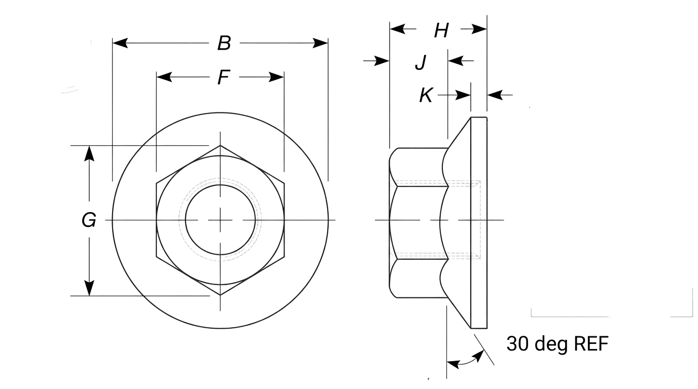
Flanged Hex Nut Dimensions
Nut Size
#6
#8
#10
#12
1/4
5/16
3/8
7/16
1/2
9/16
5/8
3/4
F
Min
0.302
0.334
0.365
0.428
0.428
0.489
0.551
0.675
0.736
0.861
0.922
1.088
Max
0.312
0.344
0.375
0.438
0.438
0.5
0.562
0.688
0.75
0.875
0.938
1.125
G
Min
0.342
0.381
0.416
0.488
0.488
0.557
0.628
0.768
0.84
0.982
1.051
1.24
Max
0.361
0.397
0.433
0.505
0.505
0.577
0.65
0.794
0.866
1.01
1.083
1.299
B
Min
0.406
0.452
0.48
0.574
0.574
0.66
0.728
0.91
1
1.155
1.248
1.46
Max
0.422
0.469
0.5
0.594
0.594
0.68
0.75
0.937
1.031
1.188
1.281
1.5
H
Min
0.156
0.187
0.203
0.222
0.222
0.268
0.33
0.375
0.437
0.483
0.545
0.627
Max
0.171
0.203
0.219
0.236
0.236
0.283
0.347
0.395
0.458
0.506
0.569
0.675
J
Min
0.1
0.13
0.13
0.14
0.14
0.17
0.23
0.26
0.31
0.35
0.4
0.46
K
Min
0.02
0.02
0.03
0.04
0.04
0.04
0.04
0.04
0.05
0.05
0.05
0.06
Note: All measurements are in inches
Disclaimer: The dimensions presented on this page are based on the applicable industry standard. However, actual product measurements may vary slightly due to manufacturing practices, material selection, surface finish, and specified tolerance classes. Buyers and sourcing professionals are encouraged to verify final specifications with the manufacturer or supplier prior to procurement, particularly for critical applications.
Legend
F – Width Across Flats: The distance between two parallel flat surfaces of the hexagonal section, used to identify the correct wrench or socket size.
G – Width Across Corners: The maximum diameter of the hexagonal portion measured from point to point, ensuring tool clearance.
B – Flange Diameter: The outer diameter of the integrated washer base, which distributes the clamping load over a wider surface area.
H – Nut Thickness: The total vertical height of the nut, from the bearing surface of the flange to the top of the hex.
J – Wrenching Length: The height of the flat hexagonal sides available for tool engagement, excluding the flange and any top chamfer.
K – Flange Thickness: The thickness of the integrated washer base at its outer edge.
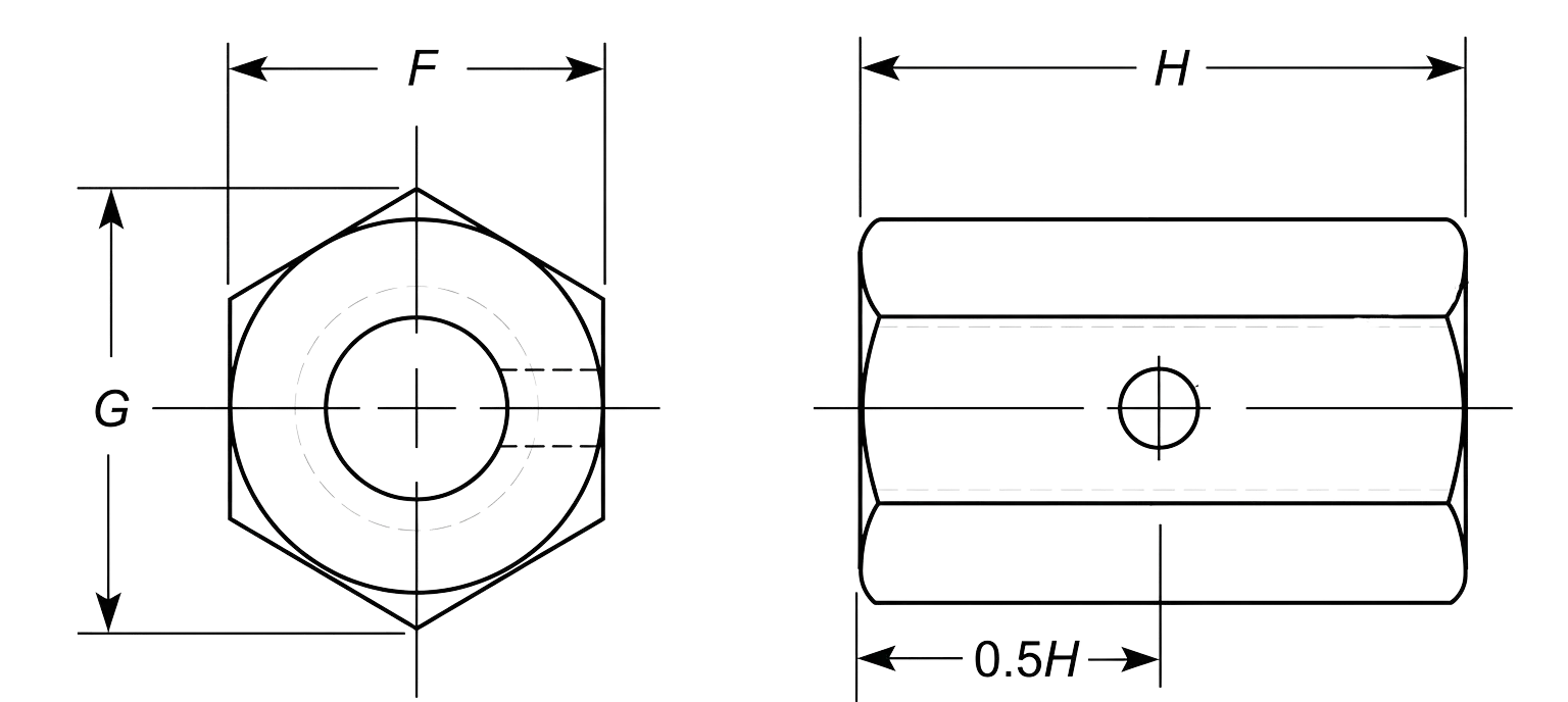
Coupling Nut Dimensions
Nut Size
#6
#8
#10
1/4
5/16
3/8
7/16
1/2
9/16
5/8
3/4
7/8
1
1-1/8
1-1/4
1-1/2
1-5/8
1-3/4
1-7/8
2
2-1/4
2-1/2
2-3/4
3
3-1/4
3-1/2
3-3/4
4
4-1/4
4-1/2
4-3/4
5
5-1/4
5-1/2
5-3/4
6
F
Min
0.302
0.302
0.302
0.428
0.489
0.551
0.607
0.663
0.782
0.782
0.963
1.212
1.325
1.45
1.575
1.95
2.481
2.662
2.844
3.025
3.388
3.75
4.112
4.475
4.838
5.2
5.562
5.925
6.288
6.65
7.012
7.375
7.738
8.1
8.462
8.825
Max
0.312
0.312
0.312
0.438
0.5
0.562
0.625
0.688
0.813
0.813
1
1.25
1.375
1.5
1.625
2
2.562
2.75
2.938
3.125
3.5
3.875
4.25
4.625
5
5.375
5.75
6.125
6.5
6.875
7.25
7.625
8
8.375
8.75
9.125
G
Min
0.344
0.344
0.344
0.488
0.557
0.628
0.692
0.756
0.891
0.891
1.097
1.382
1.511
1.653
1.825
2.275
2.828
3.305
3.242
3.448
3.862
4.275
4.688
5.101
5.515
5.928
6.34
6.754
7.168
7.581
7.994
8.408
8.821
9.234
9.647
10.06
Max
0.361
0.361
0.361
0.505
0.577
0.65
0.722
0.794
0.939
0.939
1.155
1.443
1.588
1.732
1.876
2.309
2.959
3.175
3.392
3.608
4.041
4.474
4.907
5.34
5.773
6.206
6.639
7.072
7.506
7.939
8.372
8.805
9.238
9.671
10.104
10.537
H
Min
0.47
0.595
0.711
1.69
1.69
1.69
1.69
1.69
2.067
2.067
2.19
2.44
2.69
2.94
2.94
3.44
4.83
5.21
5.58
5.95
6.7
7.44
8.19
8.94
9.68
10.43
11.17
11.92
12.67
13.42
14.16
14.91
15.65
16.4
17.15
17.89
Max
0.51
0.645
0.76
1.76
1.76
1.76
1.76
1.76
2.135
2.135
2.26
2.51
2.76
3.01
3.01
3.51
4.91
5.29
5.67
6.04
6.8
7.55
8.31
9.06
9.81
10.57
11.32
12.08
12.83
13.58
14.34
15.09
15.85
16.6
17.35
18.11
Note: All measurements are in inches
Disclaimer: The dimensions presented on this page are based on the applicable industry standard. However, actual product measurements may vary slightly due to manufacturing practices, material selection, surface finish, and specified tolerance classes. Buyers and sourcing professionals are encouraged to verify final specifications with the manufacturer or supplier prior to procurement, particularly for critical applications.
Legend
F – Width Across Flats: The distance between two parallel flat surfaces of the hexagonal nut, identifying the correct wrench or socket size required for assembly.
G – Width Across Corners: The maximum diameter of the nut measured from point to point, used to determine the necessary rotational clearance in tight spaces.
H – Nut Length: The total longitudinal height of the coupling nut, determining the maximum thread engagement available for joining two threaded rods or fasteners.