ASME B18.2.6 – Dimensions Charts
ASME B18.2.6 is the American National Standard for Fasteners for Use in Structural Applications. This standard provides complete general and dimensional data for five key structural products: heavy hex structural bolts, heavy hex nuts, hardened steel washers, compressible washer-type direct tension indicators, and twist-off-type tension control structural bolts. Use the dimension charts below to find full specifications—including head dimensions, body diameters, thread lengths, and tolerances—for high-strength fasteners conforming to ASTM A325, A490, A563, F436, F959, and F1852.
Dimensions & Size Chart

| Heavy Hex Bolt For Structural Application Dimensions | ||||||||||
|---|---|---|---|---|---|---|---|---|---|---|
| Bolt Size | 1/2 | 5/8 | 3/4 | 7/8 | 1 | 1-1/8 | 1-1/4 | 1-3/8 | 1-1/2 | |
| E | Min | 0.482 | 0.605 | 0.729 | 0.852 | 0.976 | 1.098 | 1.223 | 1.345 | 1.47 |
| Max | 0.515 | 0.642 | 0.768 | 0.895 | 1.022 | 1.149 | 1.277 | 1.404 | 1.531 | |
| F | Min | 0.85 | 1.031 | 1.212 | 1.394 | 1.575 | 1.756 | 1.938 | 2.119 | 2.3 |
| Max | 0.875 | 1.062 | 1.25 | 1.438 | 1.625 | 1.812 | 2 | 2.188 | 2.375 | |
| G | Min | 0.969 | 1.175 | 1.383 | 1.589 | 1.796 | 2.002 | 2.209 | 2.416 | 2.622 |
| Max | 1.01 | 1.227 | 1.443 | 1.66 | 1.876 | 2.093 | 2.309 | 2.526 | 2.742 | |
| H | Min | 0.302 | 0.378 | 0.455 | 0.531 | 0.591 | 0.658 | 0.749 | 0.81 | 0.902 |
| Max | 0.323 | 0.403 | 0.483 | 0.563 | 0.627 | 0.718 | 0.813 | 0.878 | 0.974 | |
| R | Min | 0.009 | 0.021 | 0.021 | 0.031 | 0.062 | 0.062 | 0.062 | 0.062 | 0.062 |
| Max | 0.031 | 0.062 | 0.062 | 0.062 | 0.093 | 0.093 | 0.093 | 0.093 | 0.093 | |
| Y | Reference | 0.19 | 0.22 | 0.25 | 0.28 | 0.31 | 0.34 | 0.38 | 0.44 | 0.44 |
| LT | Reference | 1 | 1.25 | 1.38 | 1.5 | 1.75 | 2 | 2 | 2.25 | 2.25 |
Note: All measurements are in inches
Disclaimer: The dimensions presented on this page are based on the applicable industry standard. However, actual product measurements may vary slightly due to manufacturing practices, material selection, surface finish, and specified tolerance classes. Buyers and sourcing professionals are encouraged to verify final specifications with the manufacturer or supplier prior to procurement, particularly for critical applications.
Legend
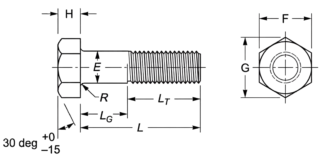
- E – Body Diameter: The thickness of the unthreaded shank used to calculate the necessary clearance hole size and determine the bolt’s overall shear strength.
- F – Width Across Flats: The distance between two parallel flat surfaces of the bolt head, used to identify the correct wrench or spanner size for installation.
- G – Width Across Corners: The maximum diameter of the hexagonal head measured from point to point, ensuring enough clearance for the tool to rotate.
- H – Head Height: The vertical thickness of the head, critical for ensuring the bolt does not protrude or interfere with moving components in tight assemblies.
- R – Radius of Underhead Fillet: The curved transition where the shank meets the head; it provides essential stress relief to prevent the head from snapping under tension.
- LT – Thread Length: The portion of the bolt featuring functional threads, determining the maximum engagement depth into a tapped hole or nut.
- L – Nominal Length: The total reach of the fastener from the under-head bearing surface to the tip.
- LG – Grip Length: The distance from the head to the first full thread (the unthreaded shear plane).
Technical Note
- Maximum Grip Gaging Length (LG, max)
- Definition: The distance parallel to the bolt axis from the underhead bearing surface to the face of a noncounterbored or noncountersunk standard GO thread ring gage, assembled by hand as far as the thread will permit.
- Calculation (Not Full Length): LG max = Lnom - LT (rounded to two decimal places).
- Calculation (Full Length): Defines the unthreaded length under the head. Shall not exceed 2.5 times the thread pitch (P) for sizes ≤ 1 in., and 3.5 times the pitch for sizes > 1 in.
- Minimum Body Length (LB, min)
- Definition: The distance parallel to the bolt axis from the underhead bearing surface to the last scratch of thread, or to the top of the extrusion angle.
- Calculation: LB min = LG max - Y (where Y is the transition thread length, rounded to two decimal places).
- LG & LB Calculation Example
- Bolt Size : 7/16-14 x 4.000 in.
- Pitch (P) : 1 ÷ 14 TPI = 0.0714 in
- LG (Max) : 4.000 - 1.380 = 2.620 in
- LB (Min) : 2.620 - Y (Transition thread length from Table 2)
- Minimum Design Grip Length : 2.620 - (5 x 0.0714) = 2.263 in
(Reflects the tolerance of minus five coarse thread pitches)
-
Length - Standard increments and permissible tolerances based on nominal bolt size and length:
- For nominal bolt sizes 1/4 to 1.00 in.:
- Up to 1.00 in. lengths: 0.06 to 0.13 in. increments with a tolerance of +0.02 / -0.03.
- Over 1.00 through 2.50 in. lengths: 0.25 in. increments with tolerances ranging from +0.02 / -0.04 for smaller diameters to +0.08 / -0.10 for 1.00 in. bolts.
- Over 2.50 through 4.00 in. lengths: 0.25 in. increments with tolerances ranging from +0.04 / -0.06 to +0.10 / -0.14.
- Over 4.00 through 6.00 in. lengths: 0.50 in. increments with tolerances ranging from +0.06 / -0.10 to +0.12 / -0.16.
- Longer than 6.00 in. lengths: 1.00 in. increments with tolerances ranging from +0.10 / -0.18 to +0.16 / -0.20.
- For nominal bolt sizes over 1.00 in.:
- Over 1.00 through 2.50 in. lengths: 0.50 in. increments with tolerances ranging from +0.12 / -0.12 to +0.18 / -0.18.
- Over 2.50 through 4.00 in. lengths: 0.50 in. increments with tolerances ranging from +0.16 / -0.16 to +0.20 / -0.20.
- Over 4.00 through 6.00 in. lengths: 0.50 in. increments with tolerances ranging from +0.18 / -0.18 to +0.22 / -0.22.
- Longer than 6.00 in. lengths: 1.00 to 2.00 in. increments with tolerances ranging from +0.22 / -0.22 to +0.24 / -0.24.
- For nominal bolt sizes 1/4 to 1.00 in.: