Unit Converter
ASME B18.21.1 – Dimensions Charts
ASME B18.21.1-2009 is the consolidated technical standard governing the dimensional requirements, physical properties, and mechanical test methods for inch-series washers, representing a merger of the previous ASME B18.21.1 and B18.22.1 specifications. The standard defines precise tolerances for three primary fastener categories: helical spring-lock washers (Regular, Heavy, Extra Duty, and High-Collar) for nominal sizes #0 through 3 inch, tooth-lock washers (Internal, External, Countersunk, and Internal/External) for sizes #2 through 1¼ inch, and plain washers (Type A, Type B, and Fender) for sizes #0 through 3 inch. All dimensional data provided in the following charts is applicable before the application of protective coatings, and materials must meet specific hardness requirements, such as 38–46 HRC for carbon steel helical sections and 40–50 HRC for tooth-lock varieties, to ensure proper mechanical performance.
Dimensions & Size Chart
| Standard Spring Lock Washer Dimensions | ||||||||||||||||||||||||||||||||||||||
|---|---|---|---|---|---|---|---|---|---|---|---|---|---|---|---|---|---|---|---|---|---|---|---|---|---|---|---|---|---|---|---|---|---|---|---|---|---|---|
| Washer Size | 2# | 3# | 4# | 5# | 6# | 8# | 10# | 12# | 1/4 | 5/16 | 3/8 | 7/16 | 1/2 | 9/16 | 5/8 | 11/16 | 3/4 | 13/16 | 7/8 | 15/16 | 1.0 | 1-1/16 | 1-1/8 | 1-3/16 | 1-1/4 | 1-5/16 | 1-3/8 | 1-7/16 | 1-1/2 | 1-5/8 | 1-3/4 | 1-7/8 | 2.0 | 2-1/4 | 2-1/2 | 2-3/4 | 3.0 | |
| D | Max | 0.094 | 0.107 | 0.12 | 0.133 | 0.148 | 0.174 | 0.2 | 0.227 | 0.26 | 0.322 | 0.385 | 0.45 | 0.512 | 0.574 | 0.641 | 0.704 | 0.766 | 0.832 | 0.894 | 0.958 | 1.024 | 1.087 | 1.153 | 1.217 | 1.28 | 1.344 | 1.408 | 1.472 | 1.534 | 1.663 | 1.789 | 1.914 | 2.039 | 2.293 | 2.543 | 2.793 | 3.043 |
| Min | 0.088 | 0.101 | 0.114 | 0.127 | 0.141 | 0.167 | 0.193 | 0.22 | 0.252 | 0.314 | 0.377 | 0.44 | 0.502 | 0.564 | 0.628 | 0.691 | 0.753 | 0.816 | 0.878 | 0.941 | 1.003 | 1.066 | 1.129 | 1.192 | 1.254 | 1.317 | 1.379 | 1.442 | 1.504 | 1.633 | 1.758 | 1.883 | 2.008 | 2.262 | 2.512 | 2.762 | 3.012 | |
| DC | Max | 0.172 | 0.195 | 0.209 | 0.236 | 0.25 | 0.293 | 0.334 | 0.377 | 0.487 | 0.583 | 0.68 | 0.776 | 0.869 | 0.965 | 1.073 | 1.17 | 1.265 | 1.363 | 1.459 | 1.556 | 1.656 | 1.751 | 1.847 | 1.943 | 2.036 | 2.133 | 2.219 | 2.324 | 2.419 | 2.553 | 2.679 | 2.811 | 2.936 | 3.221 | 3.471 | 3.824 | 4.074 |
| H | Min | 0.02 | 0.025 | 0.025 | 0.031 | 0.031 | 0.04 | 0.047 | 0.056 | 0.062 | 0.078 | 0.094 | 0.109 | 0.125 | 0.141 | 0.156 | 0.172 | 0.188 | 0.203 | 0.219 | 0.234 | 0.25 | 0.266 | 0.281 | 0.297 | 0.312 | 0.328 | 0.344 | 0.359 | 0.375 | 0.389 | 0.389 | 0.422 | 0.422 | 0.44 | 0.44 | 0.458 | 0.458 |
| N | Min | 0.035 | 0.04 | 0.04 | 0.047 | 0.047 | 0.055 | 0.062 | 0.07 | 0.109 | 0.125 | 0.141 | 0.156 | 0.171 | 0.188 | 0.203 | 0.219 | 0.234 | 0.25 | 0.266 | 0.281 | 0.297 | 0.312 | 0.328 | 0.344 | 0.359 | 0.375 | 0.391 | 0.406 | 0.422 | 0.424 | 0.424 | 0.427 | 0.427 | 0.442 | 0.442 | 0.491 | 0.491 |
| N1 | Min | 0.024 | 0.028 | 0.028 | 0.033 | 0.033 | 0.038 | 0.043 | 0.049 | 0.076 | 0.087 | 0.099 | 0.109 | 0.12 | 0.132 | 0.142 | 0.153 | 0.164 | 0.175 | 0.186 | 0.197 | 0.208 | 0.218 | 0.23 | 0.241 | 0.251 | 0.262 | 0.274 | 0.284 | 0.295 | 0.297 | 0.297 | 0.299 | 0.299 | 0.309 | 0.309 | 0.344 | 0.344 |
Note: All measurements are in inches
Disclaimer: The dimensions presented on this page are based on the applicable industry standard. However, actual product measurements may vary slightly due to manufacturing practices, material selection, surface finish, and specified tolerance classes. Buyers and sourcing professionals are encouraged to verify final specifications with the manufacturer or supplier prior to procurement, particularly for critical applications.
Legend
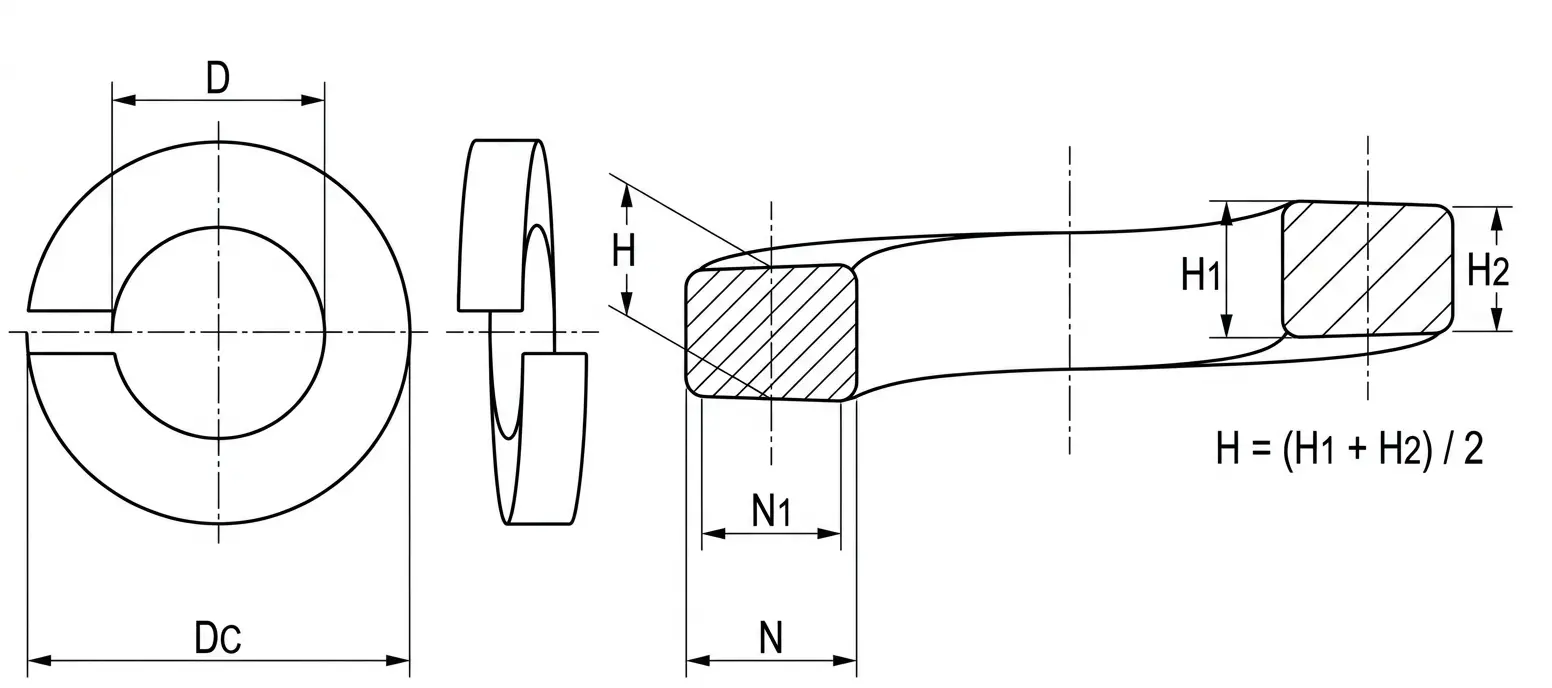
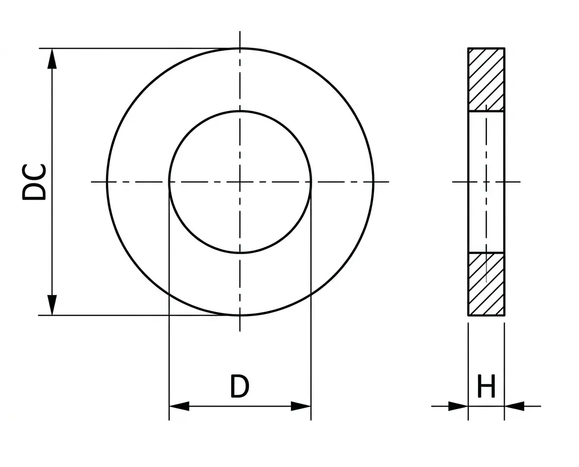
- D – Inside Diameter: The internal clearance diameter, designed to fit over the shank of the fastener.
- DC – Outside Diameter: The total width across the washer when compressed.
- H – Mean Thickness: The average vertical thickness of the washer's cross-section.
- N – Section Width: The radial width of the washer material from the inside edge to the outside edge.
- N1 – Bearing Width: The effective width of the washer surface that comes into contact with the fastener head and the mounting surface.
Technical Note
- Function: Helical spring lock washers apply a spring force between the fastener head and the substrate, maintaining tension and increasing friction to resist loosening due to vibration.
- Installation: For maximum effectiveness, the washer should be compressed until it is flat. This provides a constant "spring back" load that compensates for slight seating variations or thermal expansion.
| Heavy Spring Lock Washer Dimensions | ||||||||||||||||||||||||||||||||||||||
|---|---|---|---|---|---|---|---|---|---|---|---|---|---|---|---|---|---|---|---|---|---|---|---|---|---|---|---|---|---|---|---|---|---|---|---|---|---|---|
| Washer Size | 2# | 3# | 4# | 5# | 6# | 8# | 10# | 12# | 1/4 | 5/16 | 3/8 | 7/16 | 1/2 | 9/16 | 5/8 | 11/16 | 3/4 | 13/16 | 7/8 | 15/16 | 1.0 | 1-1/16 | 1-1/8 | 1-3/16 | 1-1/4 | 1-5/16 | 1-3/8 | 1-7/16 | 1-1/2 | 1-5/8 | 1-3/4 | 1-7/8 | 2.0 | 2-1/4 | 2-1/2 | 2-3/4 | 3.0 | |
| D | Max | 0.094 | 0.107 | 0.12 | 0.133 | 0.148 | 0.174 | 0.2 | 0.227 | 0.26 | 0.322 | 0.385 | 0.45 | 0.512 | 0.574 | 0.641 | 0.704 | 0.766 | 0.832 | 0.894 | 0.958 | 1.024 | 1.087 | 1.153 | 1.217 | 1.28 | 1.344 | 1.408 | 1.472 | 1.534 | 1.663 | 1.789 | 1.914 | 2.039 | 2.293 | 2.543 | 2.793 | 3.043 |
| Min | 0.088 | 0.101 | 0.114 | 0.127 | 0.141 | 0.167 | 0.193 | 0.22 | 0.252 | 0.314 | 0.377 | 0.44 | 0.502 | 0.564 | 0.628 | 0.691 | 0.753 | 0.816 | 0.878 | 0.941 | 1.003 | 1.066 | 1.129 | 1.192 | 1.254 | 1.317 | 1.379 | 1.442 | 1.504 | 1.633 | 1.758 | 1.883 | 2.008 | 2.262 | 2.512 | 2.762 | 3.012 | |
| DC | Max | 0.182 | 0.209 | 0.223 | 0.252 | 0.266 | 0.307 | 0.35 | 0.391 | 0.489 | 0.593 | 0.688 | 0.784 | 0.879 | 0.975 | 1.087 | 1.186 | 1.285 | 1.387 | 1.489 | 1.59 | 1.7 | 1.803 | 1.903 | 2.001 | 2.104 | 2.203 | 2.301 | 2.396 | 2.491 | 2.694 | 2.82 | 2.945 | 3.144 | 3.398 | 3.648 | 3.91 | 4.16 |
| H | Min | 0.025 | 0.031 | 0.031 | 0.04 | 0.04 | 0.047 | 0.056 | 0.063 | 0.077 | 0.097 | 0.115 | 0.133 | 0.151 | 0.17 | 0.189 | 0.207 | 0.226 | 0.246 | 0.266 | 0.284 | 0.306 | 0.326 | 0.345 | 0.364 | 0.384 | 0.403 | 0.422 | 0.44 | 0.458 | 0.458 | 0.458 | 0.458 | 0.496 | 0.496 | 0.496 | 0.526 | 0.526 |
| N | Min | 0.04 | 0.047 | 0.047 | 0.055 | 0.055 | 0.062 | 0.07 | 0.077 | 0.11 | 0.13 | 0.145 | 0.16 | 0.176 | 0.193 | 0.21 | 0.227 | 0.244 | 0.262 | 0.281 | 0.298 | 0.319 | 0.338 | 0.356 | 0.373 | 0.393 | 0.41 | 0.427 | 0.442 | 0.458 | 0.491 | 0.491 | 0.491 | 0.526 | 0.526 | 0.526 | 0.532 | 0.532 |
| N1 | Min | 0.028 | 0.033 | 0.033 | 0.038 | 0.038 | 0.043 | 0.049 | 0.054 | 0.077 | 0.091 | 0.101 | 0.112 | 0.123 | 0.135 | 0.147 | 0.159 | 0.171 | 0.183 | 0.197 | 0.209 | 0.223 | 0.237 | 0.249 | 0.261 | 0.275 | 0.287 | 0.299 | 0.309 | 0.321 | 0.344 | 0.344 | 0.344 | 0.368 | 0.368 | 0.368 | 0.372 | 0.372 |
Note: All measurements are in inches
Disclaimer: The dimensions presented on this page are based on the applicable industry standard. However, actual product measurements may vary slightly due to manufacturing practices, material selection, surface finish, and specified tolerance classes. Buyers and sourcing professionals are encouraged to verify final specifications with the manufacturer or supplier prior to procurement, particularly for critical applications.
Legend
- D – Inside Diameter: The internal clearance diameter, designed to fit over the shank of the fastener.
- DC – Outside Diameter: The total width across the washer when compressed.
- H – Mean Thickness: The average vertical thickness of the washer's cross-section.
- N – Section Width: The radial width of the washer material from the inside edge to the outside edge.
- N1 – Bearing Width: The effective width of the washer surface that comes into contact with the fastener head and the mounting surface.
Technical Note
- Function: Helical spring lock washers apply a spring force between the fastener head and the substrate, maintaining tension and increasing friction to resist loosening due to vibration.
- Installation: For maximum effectiveness, the washer should be compressed until it is flat. This provides a constant "spring back" load that compensates for slight seating variations or thermal expansion.
| Extra Duty Spring Lock Washer Dimensions | ||||||||||||||||||||||||||||||||||
|---|---|---|---|---|---|---|---|---|---|---|---|---|---|---|---|---|---|---|---|---|---|---|---|---|---|---|---|---|---|---|---|---|---|---|
| Washer Size | 2# | 3# | 4# | 5# | 6# | 8# | 10# | 12# | 1/4 | 5/16 | 3/8 | 7/16 | 1/2 | 9/16 | 5/8 | 11/16 | 3/4 | 13/16 | 7/8 | 15/16 | 1.0 | 1-1/16 | 1-1/8 | 1-3/16 | 1-1/4 | 1-5/16 | 1-3/8 | 1-7/16 | 1-1/2 | 1-5/8 | 1-3/4 | 1-7/8 | 2.0 | |
| D | Max | 0.094 | 0.107 | 0.12 | 0.133 | 0.148 | 0.174 | 0.2 | 0.227 | 0.26 | 0.322 | 0.385 | 0.45 | 0.512 | 0.574 | 0.641 | 0.704 | 0.766 | 0.832 | 0.894 | 0.958 | 1.024 | 1.087 | 1.153 | 1.217 | 1.28 | 1.344 | 1.408 | 1.472 | 1.534 | 1.663 | 1.789 | 1.914 | 2.039 |
| Min | 0.088 | 0.101 | 0.114 | 0.127 | 0.141 | 0.167 | 0.193 | 0.22 | 0.252 | 0.314 | 0.377 | 0.44 | 0.502 | 0.564 | 0.628 | 0.691 | 0.753 | 0.816 | 0.878 | 0.941 | 1.003 | 1.066 | 1.129 | 1.192 | 1.254 | 1.317 | 1.379 | 1.442 | 1.504 | 1.633 | 1.758 | 1.883 | 2.008 | |
| DC | Max | 0.208 | 0.239 | 0.253 | 0.3 | 0.314 | 0.375 | 0.434 | 0.497 | 0.533 | 0.619 | 0.738 | 0.836 | 0.935 | 1.035 | 1.151 | 1.252 | 1.355 | 1.458 | 1.571 | 1.684 | 1.794 | 1.905 | 2.013 | 2.107 | 2.222 | 2.327 | 2.429 | 2.53 | 2.627 | 2.784 | 2.902 | 3.027 | 3.156 |
| H | Min | 0.027 | 0.034 | 0.034 | 0.045 | 0.045 | 0.057 | 0.068 | 0.08 | 0.084 | 0.108 | 0.123 | 0.143 | 0.162 | 0.182 | 0.202 | 0.221 | 0.241 | 0.261 | 0.285 | 0.308 | 0.33 | 0.352 | 0.375 | 0.396 | 0.417 | 0.438 | 0.458 | 0.478 | 0.496 | 0.496 | 0.526 | 0.526 | 0.526 |
| N | Min | 0.053 | 0.062 | 0.062 | 0.079 | 0.079 | 0.096 | 0.112 | 0.13 | 0.132 | 0.143 | 0.17 | 0.186 | 0.204 | 0.223 | 0.242 | 0.26 | 0.279 | 0.298 | 0.322 | 0.345 | 0.366 | 0.389 | 0.411 | 0.431 | 0.452 | 0.472 | 0.491 | 0.509 | 0.526 | 0.526 | 0.532 | 0.532 | 0.532 |
| N1 | Min | 0.037 | 0.043 | 0.043 | 0.055 | 0.055 | 0.067 | 0.078 | 0.091 | 0.092 | 0.1 | 0.119 | 0.13 | 0.143 | 0.156 | 0.169 | 0.182 | 0.195 | 0.209 | 0.225 | 0.241 | 0.256 | 0.272 | 0.288 | 0.302 | 0.316 | 0.33 | 0.344 | 0.356 | 0.368 | 0.368 | 0.372 | 0.372 | 0.372 |
Note: All measurements are in inches
Disclaimer: The dimensions presented on this page are based on the applicable industry standard. However, actual product measurements may vary slightly due to manufacturing practices, material selection, surface finish, and specified tolerance classes. Buyers and sourcing professionals are encouraged to verify final specifications with the manufacturer or supplier prior to procurement, particularly for critical applications.
Legend
- D – Inside Diameter: The internal clearance diameter, designed to fit over the shank of the fastener.
- DC – Outside Diameter: The total width across the washer when compressed.
- H – Mean Thickness: The average vertical thickness of the washer's cross-section.
- N – Section Width: The radial width of the washer material from the inside edge to the outside edge.
- N1 – Bearing Width: The effective width of the washer surface that comes into contact with the fastener head and the mounting surface.
Technical Note
- Function: Helical spring lock washers apply a spring force between the fastener head and the substrate, maintaining tension and increasing friction to resist loosening due to vibration.
- Installation: For maximum effectiveness, the washer should be compressed until it is flat. This provides a constant "spring back" load that compensates for slight seating variations or thermal expansion.
| High Collar Spring Lock Washer Dimensions | |||||||||||||||||||||||||
|---|---|---|---|---|---|---|---|---|---|---|---|---|---|---|---|---|---|---|---|---|---|---|---|---|---|
| Washer Size | #4 | #5 | #6 | #8 | #10 | 1/4 | 5/16 | 3/8 | 7/16 | 1/2 | 5/8 | 3/4 | 7/8 | 1.0 | 1-1/8 | 1-1/4 | 1-3/8 | 1-1/2 | 1-3/4 | 2.0 | 2-1/4 | 2-1/2 | 2-3/4 | 3.0 | |
| D | Max | 0.12 | 0.133 | 0.148 | 0.174 | 0.2 | 0.26 | 0.322 | 0.385 | 0.45 | 0.512 | 0.641 | 0.766 | 0.894 | 1.024 | 1.153 | 1.28 | 1.408 | 1.534 | 1.789 | 2.039 | 2.293 | 2.543 | 2.793 | 3.043 |
| Min | 0.114 | 0.127 | 0.141 | 0.167 | 0.193 | 0.252 | 0.314 | 0.377 | 0.44 | 0.502 | 0.628 | 0.753 | 0.878 | 1.003 | 1.129 | 1.254 | 1.379 | 1.504 | 1.758 | 2.008 | 2.262 | 2.512 | 2.762 | 3.012 | |
| DC | Max | 0.173 | 0.202 | 0.216 | 0.267 | 0.294 | 0.363 | 0.457 | 0.55 | 0.644 | 0.733 | 0.917 | 1.105 | 1.291 | 1.478 | 1.663 | 1.79 | 2.031 | 2.159 | 2.596 | 2.846 | 3.345 | 3.595 | 4.095 | 4.345 |
| H | Min | 0.022 | 0.03 | 0.03 | 0.047 | 0.047 | 0.078 | 0.093 | 0.125 | 0.14 | 0.172 | 0.203 | 0.218 | 0.234 | 0.25 | 0.313 | 0.313 | 0.375 | 0.375 | 0.469 | 0.469 | 0.508 | 0.508 | 0.633 | 0.633 |
| N | Min | 0.022 | 0.03 | 0.03 | 0.042 | 0.042 | 0.047 | 0.062 | 0.076 | 0.09 | 0.103 | 0.125 | 0.154 | 0.182 | 0.208 | 0.236 | 0.236 | 0.292 | 0.292 | 0.383 | 0.383 | 0.508 | 0.508 | 0.633 | 0.633 |
| N1 | Min | 0.015 | 0.021 | 0.021 | 0.029 | 0.029 | 0.033 | 0.043 | 0.053 | 0.063 | 0.072 | 0.087 | 0.108 | 0.127 | 0.146 | 0.165 | 0.165 | 0.204 | 0.204 | 0.268 | 0.268 | 0.356 | 0.356 | 0.443 | 0.443 |
Note: All measurements are in inches
Disclaimer: The dimensions presented on this page are based on the applicable industry standard. However, actual product measurements may vary slightly due to manufacturing practices, material selection, surface finish, and specified tolerance classes. Buyers and sourcing professionals are encouraged to verify final specifications with the manufacturer or supplier prior to procurement, particularly for critical applications.
Legend
- D – Inside Diameter: The internal clearance diameter, designed to fit over the shank of the fastener.
- DC – Outside Diameter: The total width across the washer when compressed.
- H – Mean Thickness: The average vertical thickness of the washer's cross-section.
- N – Section Width: The radial width of the washer material from the inside edge to the outside edge.
- N1 – Bearing Width: The effective width of the washer surface that comes into contact with the fastener head and the mounting surface.
Technical Note
- Function: Helical spring lock washers apply a spring force between the fastener head and the substrate, maintaining tension and increasing friction to resist loosening due to vibration.
- Installation: For maximum effectiveness, the washer should be compressed until it is flat. This provides a constant "spring back" load that compensates for slight seating variations or thermal expansion.
| Internal Tooth Lock Washer Dimensions | |||||||||||||||||||||||
|---|---|---|---|---|---|---|---|---|---|---|---|---|---|---|---|---|---|---|---|---|---|---|---|
| Washer Size | 2# | 3# | 4# | 5# | 6# | 8# | 10# | 12# | 1/4 | 5/16 | 3/8 | 7/16 | 1/2 | 9/16 | 5/8 | 11/16 | 3/4 | 13/16 | 7/8 | 1.0 | 1-1/8 | 1-1/4 | |
| D | Max | 0.095 | 0.109 | 0.123 | 0.136 | 0.15 | 0.176 | 0.204 | 0.231 | 0.267 | 0.332 | 0.398 | 0.464 | 0.53 | 0.596 | 0.663 | 0.728 | 0.795 | 0.861 | 0.927 | 1.06 | 1.192 | 1.325 |
| Min | 0.089 | 0.102 | 0.115 | 0.129 | 0.141 | 0.168 | 0.195 | 0.221 | 0.256 | 0.32 | 0.384 | 0.448 | 0.512 | 0.576 | 0.64 | 0.704 | 0.769 | 0.832 | 0.894 | 1.019 | 1.144 | 1.275 | |
| DC | Max | 0.2 | 0.232 | 0.27 | 0.28 | 0.295 | 0.34 | 0.381 | 0.41 | 0.478 | 0.61 | 0.692 | 0.789 | 0.9 | 0.985 | 1.071 | 1.166 | 1.245 | 1.315 | 1.41 | 1.637 | 1.83 | 1.975 |
| Min | 0.175 | 0.215 | 0.245 | 0.255 | 0.275 | 0.325 | 0.365 | 0.394 | 0.46 | 0.594 | 0.67 | 0.74 | 0.867 | 0.957 | 1.045 | 1.13 | 1.22 | 1.29 | 1.364 | 1.59 | 1.799 | 1.921 | |
| T | Max | 0.016 | 0.016 | 0.018 | 0.02 | 0.022 | 0.023 | 0.024 | 0.027 | 0.028 | 0.034 | 0.04 | 0.04 | 0.045 | 0.045 | 0.05 | 0.05 | 0.055 | 0.055 | 0.06 | 0.067 | 0.067 | 0.067 |
| Min | 0.01 | 0.01 | 0.012 | 0.014 | 0.016 | 0.018 | 0.018 | 0.02 | 0.023 | 0.028 | 0.032 | 0.032 | 0.037 | 0.037 | 0.042 | 0.042 | 0.047 | 0.047 | 0.052 | 0.059 | 0.059 | 0.059 | |
Note: All measurements are in inches
Disclaimer: The dimensions presented on this page are based on the applicable industry standard. However, actual product measurements may vary slightly due to manufacturing practices, material selection, surface finish, and specified tolerance classes. Buyers and sourcing professionals are encouraged to verify final specifications with the manufacturer or supplier prior to procurement, particularly for critical applications.
Legend
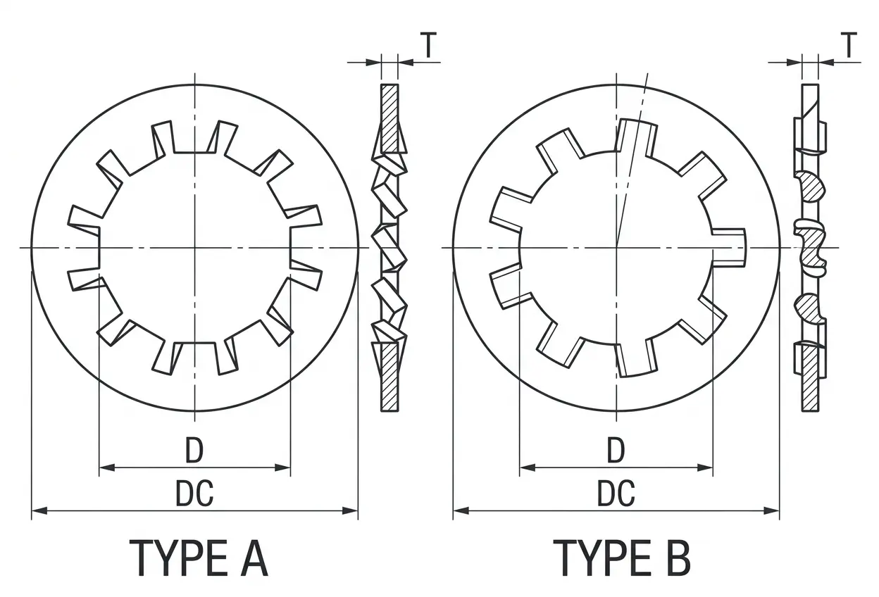
- D – Inside Diameter: The inner diameter through which the screw or bolt shank passes.
- DC – Outside Diameter: The maximum width across the outer edge of the washer body.
- T – Thickness: The vertical thickness of the material used to manufacture the washer.
Technical Note
- Application: Internal tooth lock washers are preferred when a clean, finished appearance is required, as the teeth are hidden under the fastener head. They provide high resistance to vibration and shifting by "biting" into the fastener and the bearing surface.
- Tooth Design: The teeth are twisted to create a spring-like tension that maintains clamping force, even under light loads or thermal cycles.
| Heavy Internal Tooth Lock Washer Dimensions | ||||||||||
|---|---|---|---|---|---|---|---|---|---|---|
| Washer Size | 1/4 | 5/16 | 3/8 | 7/16 | 1/2 | 9/16 | 5/8 | 3/4 | 7/8 | |
| D | Max | 0.267 | 0.332 | 0.398 | 0.464 | 0.53 | 0.596 | 0.663 | 0.795 | 0.927 |
| Min | 0.256 | 0.32 | 0.384 | 0.448 | 0.512 | 0.576 | 0.64 | 0.768 | 0.894 | |
| DC | Max | 0.536 | 0.607 | 0.748 | 0.858 | 0.924 | 1.034 | 1.135 | 1.265 | 1.447 |
| Min | 0.5 | 0.59 | 0.7 | 0.8 | 0.88 | 0.99 | 1.1 | 1.24 | 1.4 | |
| T | Max | 0.045 | 0.05 | 0.05 | 0.067 | 0.067 | 0.067 | 0.067 | 0.084 | 0.084 |
| Min | 0.035 | 0.04 | 0.042 | 0.05 | 0.055 | 0.055 | 0.059 | 0.07 | 0.075 | |
Note: All measurements are in inches
Disclaimer: The dimensions presented on this page are based on the applicable industry standard. However, actual product measurements may vary slightly due to manufacturing practices, material selection, surface finish, and specified tolerance classes. Buyers and sourcing professionals are encouraged to verify final specifications with the manufacturer or supplier prior to procurement, particularly for critical applications.
Legend
- D – Inside Diameter: The inner diameter through which the screw or bolt shank passes.
- DC – Outside Diameter: The maximum width across the outer edge of the washer body.
- T – Thickness: The vertical thickness of the material used to manufacture the washer.
Technical Note
- Application: Internal tooth lock washers are preferred when a clean, finished appearance is required, as the teeth are hidden under the fastener head. They provide high resistance to vibration and shifting by "biting" into the fastener and the bearing surface.
- Tooth Design: The teeth are twisted to create a spring-like tension that maintains clamping force, even under light loads or thermal cycles.
| External Tooth Lock Washer Dimensions | ||||||||||||||||||||
|---|---|---|---|---|---|---|---|---|---|---|---|---|---|---|---|---|---|---|---|---|
| Washer Size | #3 | #4 | #5 | #6 | #8 | #10 | #12 | 1/4 | 5/16 | 3/8 | 7/16 | 1/2 | 9/16 | 5/8 | 11/16 | 3/4 | 13/16 | 7/8 | 1.0 | |
| D | Max | 0.109 | 0.123 | 0.136 | 0.15 | 0.176 | 0.204 | 0.231 | 0.267 | 0.332 | 0.398 | 0.464 | 0.53 | 0.596 | 0.663 | 0.728 | 0.795 | 0.861 | 0.927 | 1.06 |
| Min | 0.102 | 0.115 | 0.129 | 0.141 | 0.168 | 0.195 | 0.221 | 0.256 | 0.32 | 0.384 | 0.448 | 0.513 | 0.576 | 0.641 | 0.704 | 0.768 | 0.833 | 0.897 | 1.025 | |
| DC | Max | 0.235 | 0.26 | 0.285 | 0.32 | 0.381 | 0.41 | 0.475 | 0.51 | 0.61 | 0.694 | 0.76 | 0.9 | 0.985 | 1.07 | 1.155 | 1.26 | 1.315 | 1.41 | 1.62 |
| Min | 0.22 | 0.245 | 0.27 | 0.305 | 0.365 | 0.395 | 0.46 | 0.494 | 0.588 | 0.67 | 0.74 | 0.88 | 0.96 | 1.045 | 1.13 | 1.22 | 1.29 | 1.38 | 1.59 | |
| T | Max | 0.016 | 0.018 | 0.02 | 0.022 | 0.023 | 0.024 | 0.027 | 0.028 | 0.034 | 0.04 | 0.04 | 0.045 | 0.045 | 0.05 | 0.05 | 0.055 | 0.055 | 0.06 | 0.067 |
| Min | 0.01 | 0.012 | 0.014 | 0.016 | 0.018 | 0.018 | 0.02 | 0.023 | 0.028 | 0.032 | 0.032 | 0.037 | 0.037 | 0.042 | 0.042 | 0.047 | 0.047 | 0.052 | 0.059 | |
Note: All measurements are in inches
Disclaimer: The dimensions presented on this page are based on the applicable industry standard. However, actual product measurements may vary slightly due to manufacturing practices, material selection, surface finish, and specified tolerance classes. Buyers and sourcing professionals are encouraged to verify final specifications with the manufacturer or supplier prior to procurement, particularly for critical applications.
Legend
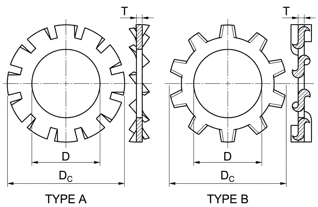
- D – Inside Diameter: The inner diameter through which the screw or bolt shank passes.
- DC – Outside Diameter: The maximum width across the outer edge of the washer body.
- T – Thickness: The vertical thickness of the material used to manufacture the washer.
Technical Note
- Application: External tooth washers are preferred for use with fasteners having larger heads (like hex or pan heads) to provide maximum torsional resistance at the outer perimeter.
- Functional Principle: The twisted teeth bite into the mating surface and the fastener head, creating a "strut" action that resists rotation and vibration.
| Countersunk External Tooth Lock Washer Dimensions | ||||||||||||
|---|---|---|---|---|---|---|---|---|---|---|---|---|
| Washer Size | #4 | #6 | #8 | #10 | #12 | 1/4 | #16 | 5/16 | 3/8 | 7/16 | 1/2 | |
| D | Max | 0.123 | 0.15 | 0.177 | 0.205 | 0.231 | 0.267 | 0.287 | 0.333 | 0.398 | 0.463 | 0.529 |
| Min | 0.113 | 0.14 | 0.167 | 0.195 | 0.22 | 0.255 | 0.273 | 0.318 | 0.383 | 0.448 | 0.512 | |
| DC | Reference | 0.213 | 0.289 | 0.322 | 0.354 | 0.421 | 0.454 | 0.505 | 0.599 | 0.765 | 0.867 | 0.976 |
| H | Max | 0.065 | 0.092 | 0.099 | 0.105 | 0.128 | 0.128 | 0.147 | 0.192 | 0.255 | 0.27 | 0.304 |
| Min | 0.05 | 0.082 | 0.083 | 0.088 | 0.118 | 0.113 | 0.137 | 0.165 | 0.242 | 0.26 | 0.294 | |
| H1 | Max | 0.019 | 0.021 | 0.021 | 0.025 | 0.025 | 0.025 | 0.028 | 0.028 | 0.034 | 0.045 | 0.045 |
| Min | 0.015 | 0.017 | 0.017 | 0.02 | 0.02 | 0.02 | 0.023 | 0.023 | 0.028 | 0.037 | 0.037 | |
Note: All measurements are in inches
Disclaimer: The dimensions presented on this page are based on the applicable industry standard. However, actual product measurements may vary slightly due to manufacturing practices, material selection, surface finish, and specified tolerance classes. Buyers and sourcing professionals are encouraged to verify final specifications with the manufacturer or supplier prior to procurement, particularly for critical applications.
Legend
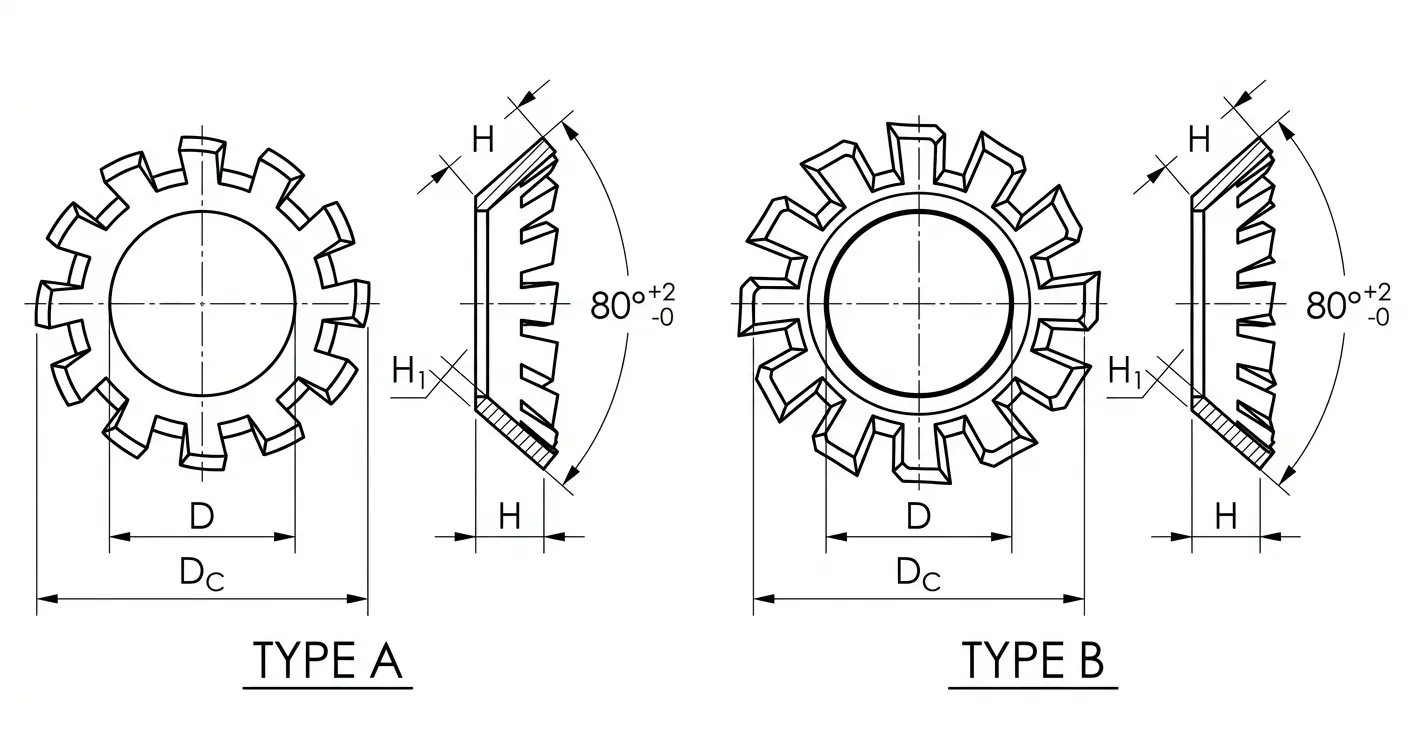
- D – Inside Diameter: The inner diameter through which the screw shank passes.
- DC – Outside Diameter: The maximum width across the outer edge of the washer teeth.
- H – Length: The total vertical height or depth of the countersunk profile.
- H1 – Thickness: The material thickness of the washer stock.
Technical Note
- Application: Specifically designed for use with 82° or 90° countersunk (flat-head) screws. These washers allow for a locking action while maintaining a flush or semi-flush appearance in the assembly.
- Locking Mechanism: The external teeth are located on the angled surface, biting into the countersunk hole of the mating part and the underside of the screw head simultaneously.
| Plain Washer (Type A) Dimensions | |||||||||||||||||||||||||||||||||||||||||||||
|---|---|---|---|---|---|---|---|---|---|---|---|---|---|---|---|---|---|---|---|---|---|---|---|---|---|---|---|---|---|---|---|---|---|---|---|---|---|---|---|---|---|---|---|---|---|
| Washer Size (Nominal) | #0 | #2 | #4 | #6 | #8 | #10 | 3/16 | #12 | 1/4 | 5/16 | 3/8 | 7/16 | 1/2 | 9/16 | 5/8 | 3/4 | 7/8 | 1 | 1-1/8 | 1-1/4 | 1-3/8 | 1-1/2 | 1-5/8 | 1-3/4 | 1-7/8 | 2.0 | 2-1/4 | 2-1/2 | 2-3/4 | 3.0 | |||||||||||||||
| Series | — | — | — | — | — | — | — | — | N | W | N | W | N | W | N | W | N | W | N | W | N | W | N | W | N | W | N | W | N | W | N | W | N | W | N | W | — | — | — | — | — | — | — | — | |
| ID | Nominal | 0.078 | 0.094 | 0.125 | 0.156 | 0.188 | 0.219 | 0.25 | 0.25 | 0.281 | 0.312 | 0.344 | 0.375 | 0.406 | 0.438 | 0.469 | 0.5 | 0.531 | 0.562 | 0.594 | 0.625 | 0.656 | 0.688 | 0.812 | 0.812 | 0.938 | 0.938 | 1.062 | 1.062 | 1.25 | 1.25 | 1.375 | 1.375 | 1.5 | 1.5 | 1.625 | 1.625 | 1.75 | 1.875 | 2 | 2.125 | 2.375 | 2.625 | 2.875 | 3.125 |
| Max | 0.078 | 0.094 | 0.133 | 0.164 | 0.196 | 0.227 | 0.265 | 0.265 | 0.296 | 0.327 | 0.359 | 0.39 | 0.421 | 0.453 | 0.484 | 0.515 | 0.546 | 0.577 | 0.609 | 0.64 | 0.686 | 0.718 | 0.842 | 0.842 | 0.968 | 0.968 | 1.092 | 1.092 | 1.28 | 1.28 | 1.405 | 1.405 | 1.53 | 1.545 | 1.655 | 1.67 | 1.795 | 1.92 | 2.045 | 2.17 | 2.42 | 2.67 | 2.94 | 3.19 | |
| Min | 0.073 | 0.089 | 0.12 | 0.151 | 0.183 | 0.214 | 0.245 | 0.245 | 0.276 | 0.307 | 0.339 | 0.37 | 0.401 | 0.433 | 0.464 | 0.495 | 0.526 | 0.557 | 0.589 | 0.62 | 0.649 | 0.681 | 0.805 | 0.805 | 0.931 | 0.931 | 1.055 | 1.055 | 1.243 | 1.243 | 1.368 | 1.368 | 1.493 | 1.49 | 1.618 | 1.615 | 1.74 | 1.865 | 1.99 | 2.115 | 2.365 | 2.615 | 2.865 | 3.115 | |
| OD | Nominal | 0.188 | 0.25 | 0.312 | 0.375 | 0.438 | 0.5 | 0.562 | 0.562 | 0.625 | 0.734 | 0.688 | 0.875 | 0.812 | 1 | 0.922 | 1.25 | 1.062 | 1.375 | 1.156 | 1.469 | 1.312 | 1.75 | 1.469 | 2 | 1.75 | 2.25 | 2 | 2.5 | 2.25 | 2.75 | 2.5 | 3 | 2.75 | 3.25 | 3 | 3.5 | 3.75 | 4 | 4.25 | 4.5 | 4.75 | 5 | 5.25 | 5.5 |
| Max | 0.188 | 0.25 | 0.32 | 0.39 | 0.453 | 0.515 | 0.577 | 0.577 | 0.64 | 0.749 | 0.703 | 0.905 | 0.827 | 1.03 | 0.937 | 1.28 | 1.092 | 1.405 | 1.186 | 1.499 | 1.342 | 1.78 | 1.499 | 2.03 | 1.78 | 2.28 | 2.03 | 2.53 | 2.28 | 2.78 | 2.53 | 3.03 | 2.78 | 3.295 | 3.03 | 3.545 | 3.795 | 4.045 | 4.295 | 4.545 | 4.795 | 5.045 | 5.315 | 5.565 | |
| Min | 0.183 | 0.245 | 0.307 | 0.37 | 0.433 | 0.495 | 0.557 | 0.557 | 0.62 | 0.727 | 0.681 | 0.868 | 0.805 | 0.993 | 0.915 | 1.243 | 1.055 | 1.368 | 1.149 | 1.462 | 1.305 | 1.743 | 1.462 | 1.993 | 1.743 | 2.243 | 1.993 | 2.493 | 2.243 | 2.743 | 2.493 | 2.993 | 2.743 | 3.24 | 2.993 | 3.49 | 3.74 | 3.99 | 4.24 | 4.49 | 4.74 | 4.99 | 5.24 | 5.49 | |
| THICK | Nominal | 0.02 | 0.02 | 0.032 | 0.049 | 0.049 | 0.049 | 0.049 | 0.065 | 0.065 | 0.065 | 0.065 | 0.083 | 0.065 | 0.083 | 0.065 | 0.083 | 0.095 | 0.109 | 0.095 | 0.109 | 0.095 | 0.134 | 0.134 | 0.148 | 0.134 | 0.165 | 0.134 | 0.165 | 0.134 | 0.165 | 0.165 | 0.165 | 0.165 | 0.18 | 0.165 | 0.18 | 0.18 | 0.18 | 0.18 | 0.18 | 0.22 | 0.238 | 0.259 | 0.284 |
| Max | 0.025 | 0.025 | 0.04 | 0.065 | 0.065 | 0.065 | 0.065 | 0.08 | 0.08 | 0.08 | 0.08 | 0.104 | 0.08 | 0.104 | 0.08 | 0.104 | 0.121 | 0.132 | 0.121 | 0.132 | 0.121 | 0.16 | 0.16 | 0.177 | 0.16 | 0.192 | 0.16 | 0.192 | 0.16 | 0.192 | 0.192 | 0.192 | 0.192 | 0.213 | 0.192 | 0.213 | 0.213 | 0.213 | 0.213 | 0.213 | 0.248 | 0.28 | 0.31 | 0.327 | |
| Min | 0.016 | 0.016 | 0.025 | 0.036 | 0.036 | 0.036 | 0.036 | 0.051 | 0.051 | 0.051 | 0.051 | 0.064 | 0.051 | 0.064 | 0.051 | 0.064 | 0.074 | 0.086 | 0.074 | 0.086 | 0.074 | 0.108 | 0.108 | 0.122 | 0.108 | 0.136 | 0.108 | 0.136 | 0.108 | 0.136 | 0.136 | 0.136 | 0.136 | 0.153 | 0.136 | 0.153 | 0.153 | 0.153 | 0.153 | 0.153 | 0.193 | 0.21 | 0.228 | 0.249 | |
Note: All measurements are in inches
Disclaimer: The dimensions presented on this page are based on the applicable industry standard. However, actual product measurements may vary slightly due to manufacturing practices, material selection, surface finish, and specified tolerance classes. Buyers and sourcing professionals are encouraged to verify final specifications with the manufacturer or supplier prior to procurement, particularly for critical applications.
Legend
- D – Inside Diameter: The nominal diameter of the inner hole, typically slightly larger than the bolt diameter to provide clearance.
- DC – Outside Diameter: The total external width of the washer, which determines the surface area available for load distribution.
- H – Thickness: The vertical height of the washer, which provides the necessary spacing and structural rigidity for the assembly.
Technical Note
- Series Classification: Narrow (N) series are intended for use with small diameter heads (like cheese or fillister heads). Wide (W) series provide a larger bearing surface for load distribution.
- Standard: Dimensions per ASME B18.21.1 Type A.
| Plain Washer (Type B) Dimensions | |||||||||||||||||||||||||||||||||||||||||||||||||||||||||||||||||||||||||||||||||||||||||||||||||
|---|---|---|---|---|---|---|---|---|---|---|---|---|---|---|---|---|---|---|---|---|---|---|---|---|---|---|---|---|---|---|---|---|---|---|---|---|---|---|---|---|---|---|---|---|---|---|---|---|---|---|---|---|---|---|---|---|---|---|---|---|---|---|---|---|---|---|---|---|---|---|---|---|---|---|---|---|---|---|---|---|---|---|---|---|---|---|---|---|---|---|---|---|---|---|---|---|---|
| Washer Size (Nominal) | #0 | #1 | #2 | #3 | #4 | #5 | #6 | #8 | #10 | #12 | 1/4 | 5/16 | 3/8 | 7/16 | 1/2 | 9/16 | 5/8 | 3/4 | 7/8 | 1.0 | 1-1/8 | 1-1/4 | 1-3/8 | 1-1/2 | 1-5/8 | 1-3/4 | 1-7/8 | 2.0 | 2-1/4 | 2-1/2 | 2-3/4 | 3.0 | |||||||||||||||||||||||||||||||||||||||||||||||||||||||||||||||||
| Series | FBN | FBR | FBW | FBN | FBR | FBW | FBN | FBR | FBW | FBN | FBR | FBW | FBN | FBR | FBW | FBN | FBR | FBW | FBN | FBR | FBW | FBN | FBR | FBW | FBN | FBR | FBW | FBN | FBR | FBW | FBN | FBR | FBW | FBN | FBR | FBW | FBN | FBR | FBW | FBN | FBR | FBW | FBN | FBR | FBW | FBN | FBR | FBW | FBN | FBR | FBW | FBN | FBR | FBW | FBN | FBR | FBW | FBN | FBR | FBW | FBN | FBR | FBW | FBN | FBR | FBW | FBN | FBR | FBW | FBN | FBR | FBW | FBN | FBR | FBW | FBN | FBR | FBW | FBN | FBR | FBW | FBN | FBR | FBW | FBN | FBR | FBW | FBN | FBR | FBW | FBN | FBR | FBW | FBN | FBR | FBW | |
| ID | Nominal | 0.068 | 0.068 | 0.068 | 0.084 | 0.084 | 0.084 | 0.094 | 0.094 | 0.094 | 0.109 | 0.109 | 0.109 | 0.125 | 0.125 | 0.125 | 0.141 | 0.141 | 0.141 | 0.156 | 0.156 | 0.156 | 0.188 | 0.188 | 0.188 | 0.203 | 0.203 | 0.203 | 0.234 | 0.234 | 0.234 | 0.281 | 0.281 | 0.281 | 0.344 | 0.344 | 0.344 | 0.406 | 0.406 | 0.406 | 0.469 | 0.469 | 0.469 | 0.531 | 0.531 | 0.531 | 0.594 | 0.594 | 0.594 | 0.656 | 0.656 | 0.656 | 0.812 | 0.812 | 0.812 | 0.938 | 0.938 | 0.938 | 1.062 | 1.062 | 1.062 | 1.188 | 1.188 | 1.188 | 1.312 | 1.312 | 1.312 | 1.438 | 1.438 | 1.438 | 1.562 | 1.562 | 1.562 | 1.75 | 1.75 | 1.75 | 1.875 | 1.875 | 1.875 | 2 | 2 | 2 | 2.125 | 2.125 | 2.125 | 2.375 | 2.375 | 2.375 | 2.625 | 2.625 | 2.625 | 2.875 | 2.875 | 2.875 | 3.125 | 3.125 | 3.125 |
| Max | 0.068 | 0.068 | 0.068 | 0.084 | 0.084 | 0.084 | 0.094 | 0.094 | 0.094 | 0.109 | 0.109 | 0.117 | 0.125 | 0.133 | 0.133 | 0.141 | 0.149 | 0.149 | 0.156 | 0.164 | 0.164 | 0.196 | 0.196 | 0.196 | 0.211 | 0.211 | 0.211 | 0.242 | 0.242 | 0.242 | 0.296 | 0.296 | 0.296 | 0.359 | 0.359 | 0.359 | 0.421 | 0.421 | 0.421 | 0.484 | 0.484 | 0.484 | 0.546 | 0.546 | 0.546 | 0.609 | 0.609 | 0.609 | 0.686 | 0.686 | 0.686 | 0.842 | 0.842 | 0.842 | 0.968 | 0.968 | 0.968 | 1.092 | 1.092 | 1.092 | 1.218 | 1.218 | 1.218 | 1.342 | 1.342 | 1.357 | 1.468 | 1.468 | 1.483 | 1.592 | 1.607 | 1.607 | 1.78 | 1.795 | 1.795 | 1.905 | 1.92 | 1.92 | 2.045 | 2.045 | 2.045 | 2.17 | 2.17 | 2.17 | 2.42 | 2.42 | 2.44 | 2.67 | 2.69 | 2.69 | 2.92 | 2.94 | 2.94 | 3.19 | 3.19 | 3.19 | |
| Min | 0.063 | 0.063 | 0.063 | 0.079 | 0.079 | 0.079 | 0.089 | 0.089 | 0.089 | 0.104 | 0.104 | 0.104 | 0.12 | 0.12 | 0.12 | 0.136 | 0.136 | 0.136 | 0.151 | 0.151 | 0.151 | 0.183 | 0.183 | 0.183 | 0.198 | 0.198 | 0.198 | 0.229 | 0.229 | 0.229 | 0.276 | 0.276 | 0.276 | 0.339 | 0.339 | 0.339 | 0.401 | 0.401 | 0.401 | 0.464 | 0.464 | 0.464 | 0.526 | 0.526 | 0.526 | 0.589 | 0.589 | 0.589 | 0.649 | 0.649 | 0.649 | 0.805 | 0.805 | 0.805 | 0.931 | 0.931 | 0.931 | 1.055 | 1.055 | 1.055 | 1.181 | 1.181 | 1.181 | 1.305 | 1.305 | 1.302 | 1.431 | 1.431 | 1.428 | 1.555 | 1.552 | 1.552 | 1.743 | 1.74 | 1.74 | 1.868 | 1.865 | 1.865 | 1.99 | 1.99 | 1.99 | 2.115 | 2.115 | 2.115 | 2.365 | 2.365 | 2.365 | 2.615 | 2.615 | 2.615 | 2.865 | 2.865 | 2.865 | 3.115 | 3.115 | 3.115 | |
| OD | Nominal | 0.125 | 0.188 | 0.25 | 0.156 | 0.219 | 0.281 | 0.188 | 0.25 | 0.344 | 0.219 | 0.312 | 0.406 | 0.25 | 0.375 | 0.438 | 0.281 | 0.406 | 0.5 | 0.312 | 0.438 | 0.562 | 0.375 | 0.5 | 0.625 | 0.406 | 0.562 | 0.734 | 0.438 | 0.625 | 0.875 | 0.5 | 0.734 | 1 | 0.625 | 0.875 | 1.125 | 0.734 | 1 | 1.25 | 0.875 | 1.125 | 1.469 | 1 | 1.25 | 1.75 | 1.125 | 1.469 | 2 | 1.25 | 1.75 | 2.25 | 1.375 | 2 | 2.5 | 1.469 | 2.25 | 2.75 | 1.75 | 2.5 | 3 | 2 | 2.75 | 3.25 | 2.25 | 3 | 3.5 | 2.5 | 3.25 | 3.75 | 2.75 | 3.5 | 4 | 3 | 3.75 | 4.25 | 3.25 | 4 | 4.5 | 3.5 | 4.25 | 4.75 | 3.75 | 4.5 | 5 | 4 | 5 | 5.5 | 4.5 | 5.5 | 6 | 5 | 6 | 6.5 | 5.5 | 6.5 | 7 |
| Max | 0.125 | 0.188 | 0.25 | 0.156 | 0.219 | 0.281 | 0.188 | 0.25 | 0.344 | 0.219 | 0.312 | 0.414 | 0.25 | 0.383 | 0.446 | 0.281 | 0.414 | 0.508 | 0.312 | 0.446 | 0.57 | 0.383 | 0.508 | 0.64 | 0.414 | 0.57 | 0.749 | 0.446 | 0.64 | 0.89 | 0.515 | 0.749 | 1.015 | 0.64 | 0.89 | 1.14 | 0.749 | 1.015 | 1.28 | 0.89 | 1.14 | 1.499 | 1.015 | 1.28 | 1.78 | 1.14 | 1.499 | 2.03 | 1.28 | 1.78 | 2.28 | 1.405 | 2.03 | 2.53 | 1.499 | 2.28 | 2.78 | 1.78 | 2.53 | 3.03 | 2.03 | 2.78 | 3.28 | 2.28 | 3.03 | 3.545 | 2.53 | 3.28 | 3.795 | 2.78 | 3.545 | 4.045 | 3.03 | 3.795 | 4.295 | 3.28 | 4.045 | 4.545 | 3.545 | 4.295 | 4.795 | 3.795 | 4.545 | 5.045 | 4.045 | 5.045 | 5.565 | 4.545 | 5.565 | 6.065 | 5.045 | 6.065 | 6.565 | 5.565 | 6.565 | 7.065 | |
| Min | 0.12 | 0.183 | 0.245 | 0.151 | 0.214 | 0.276 | 0.183 | 0.245 | 0.339 | 0.214 | 0.307 | 0.401 | 0.245 | 0.37 | 0.433 | 0.276 | 0.401 | 0.495 | 0.307 | 0.433 | 0.557 | 0.37 | 0.495 | 0.62 | 0.401 | 0.557 | 0.727 | 0.433 | 0.62 | 0.868 | 0.495 | 0.727 | 0.993 | 0.62 | 0.868 | 1.118 | 0.727 | 0.993 | 1.243 | 0.868 | 1.118 | 1.462 | 0.993 | 1.243 | 1.743 | 1.118 | 1.462 | 1.993 | 1.243 | 1.743 | 2.243 | 1.368 | 1.993 | 2.493 | 1.462 | 2.243 | 2.743 | 1.743 | 2.493 | 2.993 | 1.993 | 2.743 | 3.243 | 2.243 | 2.993 | 3.49 | 2.493 | 3.243 | 3.74 | 2.743 | 3.49 | 3.99 | 2.993 | 3.74 | 4.24 | 3.243 | 3.99 | 4.49 | 3.49 | 4.24 | 4.74 | 3.74 | 4.49 | 4.99 | 3.99 | 4.99 | 5.49 | 4.49 | 5.49 | 5.99 | 4.99 | 5.99 | 6.49 | 5.49 | 6.49 | 6.99 | |
| THICK | Nominal | 0.025 | 0.025 | 0.025 | 0.025 | 0.025 | 0.032 | 0.025 | 0.032 | 0.032 | 0.025 | 0.032 | 0.04 | 0.032 | 0.04 | 0.04 | 0.032 | 0.04 | 0.04 | 0.032 | 0.04 | 0.04 | 0.04 | 0.04 | 0.063 | 0.04 | 0.04 | 0.063 | 0.04 | 0.063 | 0.063 | 0.063 | 0.063 | 0.063 | 0.063 | 0.063 | 0.063 | 0.063 | 0.063 | 0.1 | 0.063 | 0.063 | 0.1 | 0.063 | 0.1 | 0.1 | 0.063 | 0.1 | 0.1 | 0.1 | 0.1 | 0.16 | 0.1 | 0.1 | 0.16 | 0.1 | 0.16 | 0.16 | 0.1 | 0.16 | 0.16 | 0.1 | 0.16 | 0.16 | 0.16 | 0.16 | 0.25 | 0.16 | 0.16 | 0.25 | 0.16 | 0.25 | 0.25 | 0.16 | 0.25 | 0.25 | 0.16 | 0.25 | 0.25 | 0.25 | 0.25 | 0.25 | 0.25 | 0.25 | 0.25 | 0.25 | 0.25 | 0.375 | 0.25 | 0.375 | 0.375 | 0.25 | 0.375 | 0.375 | 0.375 | 0.375 | 0.375 |
| Max | 0.028 | 0.028 | 0.028 | 0.028 | 0.028 | 0.036 | 0.028 | 0.036 | 0.036 | 0.028 | 0.036 | 0.045 | 0.036 | 0.045 | 0.045 | 0.036 | 0.045 | 0.045 | 0.036 | 0.045 | 0.045 | 0.045 | 0.045 | 0.071 | 0.045 | 0.045 | 0.071 | 0.045 | 0.071 | 0.071 | 0.071 | 0.071 | 0.071 | 0.071 | 0.071 | 0.071 | 0.071 | 0.071 | 0.112 | 0.071 | 0.071 | 0.112 | 0.071 | 0.112 | 0.112 | 0.071 | 0.112 | 0.112 | 0.112 | 0.112 | 0.174 | 0.112 | 0.112 | 0.174 | 0.112 | 0.174 | 0.174 | 0.112 | 0.174 | 0.174 | 0.112 | 0.174 | 0.174 | 0.174 | 0.174 | 0.266 | 0.174 | 0.174 | 0.266 | 0.174 | 0.266 | 0.266 | 0.174 | 0.266 | 0.266 | 0.174 | 0.266 | 0.266 | 0.266 | 0.266 | 0.266 | 0.266 | 0.266 | 0.266 | 0.266 | 0.266 | 0.393 | 0.266 | 0.393 | 0.393 | 0.266 | 0.393 | 0.393 | 0.393 | 0.393 | 0.393 | |
| Min | 0.022 | 0.022 | 0.022 | 0.022 | 0.022 | 0.028 | 0.022 | 0.028 | 0.028 | 0.022 | 0.028 | 0.036 | 0.028 | 0.036 | 0.036 | 0.028 | 0.036 | 0.036 | 0.028 | 0.036 | 0.036 | 0.036 | 0.036 | 0.056 | 0.036 | 0.036 | 0.056 | 0.036 | 0.056 | 0.056 | 0.056 | 0.056 | 0.056 | 0.056 | 0.056 | 0.056 | 0.056 | 0.056 | 0.09 | 0.056 | 0.056 | 0.09 | 0.056 | 0.09 | 0.09 | 0.056 | 0.09 | 0.09 | 0.09 | 0.09 | 0.146 | 0.09 | 0.09 | 0.146 | 0.09 | 0.146 | 0.146 | 0.09 | 0.146 | 0.146 | 0.09 | 0.146 | 0.146 | 0.146 | 0.146 | 0.234 | 0.146 | 0.146 | 0.234 | 0.146 | 0.234 | 0.234 | 0.146 | 0.234 | 0.234 | 0.146 | 0.234 | 0.234 | 0.234 | 0.234 | 0.234 | 0.234 | 0.234 | 0.234 | 0.234 | 0.234 | 0.357 | 0.234 | 0.357 | 0.357 | 0.234 | 0.357 | 0.357 | 0.357 | 0.357 | 0.357 | |
Note: All measurements are in inches
Disclaimer: The dimensions presented on this page are based on the applicable industry standard. However, actual product measurements may vary slightly due to manufacturing practices, material selection, surface finish, and specified tolerance classes. Buyers and sourcing professionals are encouraged to verify final specifications with the manufacturer or supplier prior to procurement, particularly for critical applications.
Legend
- D – Inside Diameter: The nominal diameter of the inner hole, typically slightly larger than the bolt diameter to provide clearance.
- DC – Outside Diameter: The total external width of the washer, which determines the surface area available for load distribution.
- H – Thickness: The vertical height of the washer, which provides the necessary spacing and structural rigidity for the assembly.
- Series Codes: FBN (Narrow), FBR (Regular), FBW (Wide).
Technical Note
- Type B Classification: Type B plain washers are precision washers
- Precision Fit: These provide tighter tolerances than Type A washers for high-precision fastener applications.
| Fender Washer Dimensions | ||||||||||||||||||||||||||||||
|---|---|---|---|---|---|---|---|---|---|---|---|---|---|---|---|---|---|---|---|---|---|---|---|---|---|---|---|---|---|---|
| Washer Size | 1/8×5/8 | 1/8×3/4 | 5/32×7/8 | 3/16×3/4 | 3/16×1 | 3/16×1-1/4 | 3/16×1-1/2 | 1/4×1 | 1/4×1-1/4 | 1/4×1-1/2 | 1/4×1-3/4 | 1/4×2 | 5/16×7/8 | 5/16×1 | 5/16×1-1/4 | 5/16×1-1/2 | 5/16×1-3/4 | 5/16×1-5/8 | 5/16×2 | 3/8×1-1/4 | 3/8×1-1/2 | 3/8×1-3/4 | 3/8×1-5/8 | 3/8×2 | 1/2×1-1/4 | 1/2×1-1/2 | 1/2×1-3/4 | 1/2×2 | 1/2×2-1/2 | |
| D | Nominal | 0.16 | 0.16 | 0.19 | 0.19 | 0.19 | 0.19 | 0.19 | 0.285 | 0.285 | 0.285 | 0.285 | 0.285 | 0.348 | 0.348 | 0.348 | 0.348 | 0.348 | 0.348 | 0.348 | 0.41 | 0.41 | 0.41 | 0.41 | 0.41 | 0.535 | 0.535 | 0.535 | 0.535 | 0.535 |
| Min | 0.15 | 0.15 | 0.182 | 0.213 | 0.213 | 0.213 | 0.213 | 0.275 | 0.275 | 0.275 | 0.275 | 0.275 | 0.338 | 0.338 | 0.338 | 0.338 | 0.338 | 0.338 | 0.338 | 0.4 | 0.4 | 0.4 | 0.4 | 0.4 | 0.525 | 0.525 | 0.525 | 0.525 | 0.525 | |
| Max | 0.17 | 0.17 | 0.201 | 0.233 | 0.233 | 0.233 | 0.233 | 0.295 | 0.295 | 0.295 | 0.295 | 0.295 | 0.358 | 0.358 | 0.358 | 0.358 | 0.358 | 0.358 | 0.358 | 0.42 | 0.42 | 0.42 | 0.42 | 0.42 | 0.545 | 0.545 | 0.545 | 0.545 | 0.545 | |
| DC | Nominal | 0.625 | 0.75 | 0.875 | 0.75 | 1 | 1.25 | 1.5 | 1 | 1.25 | 1.5 | 1.761 | 2 | 0.875 | 1 | 1.25 | 1.5 | 1.75 | 1.625 | 2 | 1.25 | 1.5 | 1.75 | 1.625 | 2 | 1.25 | 1.5 | 1.75 | 2 | 2.5 |
| Min | 0.617 | 0.742 | 0.867 | 0.742 | 0.992 | 1.242 | 1.492 | 0.992 | 1.242 | 1.492 | 1.742 | 1.992 | 0.867 | 0.992 | 1.242 | 1.492 | 1.742 | 1.617 | 1.992 | 1.242 | 1.492 | 1.742 | 1.617 | 1.992 | 1.242 | 1.492 | 1.742 | 1.992 | 2.492 | |
| Max | 0.654 | 0.779 | 0.904 | 0.779 | 1.018 | 1.279 | 1.529 | 1.029 | 1.279 | 1.529 | 1.779 | 2.029 | 0.904 | 1.029 | 1.279 | 1.529 | 1.779 | 1.654 | 2.029 | 1.279 | 1.529 | 1.779 | 1.654 | 2.029 | 1.279 | 1.529 | 1.779 | 2.029 | 2.529 | |
| H | Nominal | 0.065 | 0.065 | 0.065 | 0.065 | 0.065 | 0.065 | 0.065 | 0.065 | 0.065 | 0.065 | 0.065 | 0.065 | 0.065 | 0.065 | 0.065 | 0.065 | 0.065 | 0.065 | 0.065 | 0.065 | 0.065 | 0.065 | 0.065 | 0.065 | 0.065 | 0.065 | 0.065 | 0.065 | 0.065 |
| Min | 0.047 | 0.047 | 0.047 | 0.047 | 0.047 | 0.047 | 0.047 | 0.047 | 0.047 | 0.047 | 0.047 | 0.047 | 0.047 | 0.047 | 0.047 | 0.047 | 0.047 | 0.047 | 0.047 | 0.047 | 0.047 | 0.047 | 0.047 | 0.047 | 0.047 | 0.047 | 0.047 | 0.047 | 0.047 | |
| Max | 0.08 | 0.08 | 0.08 | 0.08 | 0.08 | 0.08 | 0.08 | 0.08 | 0.08 | 0.08 | 0.08 | 0.08 | 0.08 | 0.08 | 0.08 | 0.08 | 0.08 | 0.08 | 0.08 | 0.08 | 0.08 | 0.08 | 0.08 | 0.08 | 0.08 | 0.08 | 0.08 | 0.08 | 0.08 | |
Note: All measurements are in inches
Disclaimer: The dimensions presented on this page are based on the applicable industry standard. However, actual product measurements may vary slightly due to manufacturing practices, material selection, surface finish, and specified tolerance classes. Buyers and sourcing professionals are encouraged to verify final specifications with the manufacturer or supplier prior to procurement, particularly for critical applications.
Legend
- D – Inside Diameter: The nominal diameter of the inner hole, typically slightly larger than the bolt diameter to provide clearance.
- DC – Outside Diameter: The total external width of the washer, which determines the surface area available for load distribution.
- H – Thickness: The vertical height of the washer, which provides the necessary spacing and structural rigidity for the assembly.
Technical Note
- Fender Washer Designation: Fender washers are typically identified by a dual-dimension format, such as "1/8 × 5/8". The first value refers to the nominal Inside Diameter (D), while the second value represents the Outside Diameter (DC).
- Application: Fender washers are designed to spread the load of a fastener over a wide area. They are commonly used in auto body repair (hence the name "fender"), sheet metal work, and plumbing where the mounting material is thin or prone to tearing.
- Design Benefit: By increasing the surface area, fender washers prevent the head of a bolt or a nut from pulling through the substrate under high tension or vibration.