ASME B18.3 is the American National Standard for Inch Series hexagon socket cap screws, shoulder screws, and set screws. It provides complete dimensional and general data for high-strength precision fasteners, including socket head cap screws (cap, low cap, button head, and flat countersunk), shoulder screws, and set screws with various point styles like cup, flat, oval, cone, and half dog. Use the dimension charts below to find full specifications for every fastener category and hexagon key size covered under the standard.
Dimensions & Size Chart
Cap Head Screw Dimensions
Screw Size
#0
#1
#2
#3
#4
#5
#6
#8
#10
#12
1/4
5/16
3/8
7/16
1/2
9/16
5/8
3/4
7/8
1
1-1/8
1-1/4
1-3/8
1-1/2
1-3/4
2
2-1/4
2-1/2
2-3/4
3
3-1/4
3-1/2
3-3/4
4
D
Min
0.0568
0.0695
0.0822
0.0949
0.1075
0.1202
0.1329
0.1585
0.184
0.2095
0.2435
0.3053
0.3678
0.4294
0.4919
0.5538
0.6163
0.7406
0.8647
0.9886
1.1086
1.2336
1.3568
1.4818
1.7295
1.978
2.228
2.4762
2.7262
2.9762
3.2262
3.4762
3.7262
3.9762
Max
0.06
0.073
0.086
0.099
0.112
0.125
0.138
0.164
0.19
0.216
0.25
0.3125
0.375
0.4375
0.5
0.5625
0.625
0.75
0.875
1
1.125
1.25
1.375
1.5
1.75
2
2.25
2.5
2.75
3
3.25
3.5
3.75
4
A
Min
0.091
0.112
0.134
0.154
0.176
0.198
0.216
0.257
0.298
0.314
0.354
0.446
0.54
0.631
0.725
0.827
0.914
1.094
1.291
1.476
1.665
1.852
2.038
2.224
2.597
2.97
3.344
3.717
4.09
4.464
4.837
5.211
5.584
5.958
Max
0.096
0.118
0.14
0.161
0.183
0.205
0.226
0.27
0.312
0.324
0.375
0.469
0.562
0.656
0.75
0.843
0.938
1.125
1.312
1.5
1.688
1.875
2.062
2.25
2.625
3
3.375
3.75
4.125
4.5
4.875
5.25
5.625
6
H
Min
0.057
0.07
0.083
0.095
0.108
0.121
0.134
0.159
0.185
0.21
0.244
0.306
0.368
0.43
0.492
0.554
0.616
0.74
0.864
0.988
1.111
1.236
1.36
1.485
1.734
1.983
2.232
2.481
2.73
2.979
3.228
3.478
3.727
3.976
Max
0.06
0.073
0.086
0.099
0.112
0.125
0.138
0.164
0.19
0.216
0.25
0.312
0.375
0.438
0.5
0.562
0.625
0.75
0.875
1
1.125
1.25
1.375
1.5
1.75
2
2.25
2.5
2.75
3
3.25
3.5
3.75
4
C
Max
0.004
0.005
0.008
0.008
0.009
0.012
0.013
0.014
0.018
0.022
0.025
0.033
0.04
0.047
0.055
0.062
0.07
0.085
0.1
0.114
0.129
0.144
0.16
0.176
0.207
0.238
0.269
0.3
0.332
0.363
0.394
0.426
0.458
0.489
J
Decimal
0.05
0.062
0.078
0.078
0.094
0.094
0.109
0.141
0.156
0.156
0.188
0.25
0.312
0.375
0.375
0.437
0.5
0.625
0.75
0.75
0.875
0.875
1
1
1.25
1.5
1.75
1.75
2
2.25
2.25
2.75
2.75
3
Nominal
—
1/6
5/64
5/64
3/32
3/32
7/64
9/64
5/32
5/32
3/16
1/4
5/16
3/8
3/8
7/16
1/2
5/8
3/4
3/4
7/8
7/8
1
1
1-1/4
1–1/2
1-3/4
1-3/4
2
2-1/4
2-1/4
2-3/4
2-3/4
3
T
Min
0.025
0.031
0.038
0.044
0.051
0.057
0.064
0.077
0.09
0.103
0.12
0.151
0.182
0.213
0.245
0.276
0.307
0.37
0.432
0.495
0.557
0.62
0.682
0.745
0.87
0.995
1.12
1.245
1.37
1.495
1.62
1.745
1.87
1.995
G
Min
0.02
0.025
0.029
0.034
0.038
0.043
0.047
0.056
0.065
0.082
0.095
0.119
0.143
0.166
0.19
0.214
0.238
0.285
0.333
0.38
0.428
0.475
0.523
0.57
0.665
0.76
0.855
0.95
1.045
1.14
1.235
1.33
1.425
1.52
K
Max
0.007
0.007
0.007
0.007
0.008
0.008
0.008
0.008
0.008
0.01
0.01
0.01
0.01
0.015
0.015
0.015
0.015
0.015
0.02
0.02
0.02
0.02
0.02
0.02
0.02
0.02
0.036
0.036
0.036
0.036
0.036
0.036
0.036
0.036
F
Min
0.062
0.075
0.09
0.102
0.117
0.132
0.144
0.172
0.202
—
0.261
0.329
0.397
0.465
0.531
—
0.664
0.8
0.932
1.068
1.198
1.333
1.466
1.601
1.869
2.128
2.398
2.662
2.936
3.206
3.476
3.746
4.016
4.286
Max
0.074
0.087
0.102
0.115
0.13
0.145
0.158
0.188
0.218
—
0.278
0.347
0.415
0.484
0.552
—
0.689
0.828
0.963
1.1
1.235
1.37
1.505
1.64
1.91
2.18
2.45
2.72
2.99
3.26
3.53
3.8
4.07
4.34
LT
Min
0.5
0.62
0.62
0.62
0.75
0.75
0.75
0.88
0.88
0.88
1
1.12
1.25
1.38
1.5
1.5
1.75
2
2.25
2.5
2.81
3.12
3.44
3.75
4.38
5
5.62
6.25
6.88
7.5
8.12
8.75
9.38
10
Max
0.62
0.77
0.8
0.83
0.99
1
1.05
1.19
1.27
1.27
1.5
1.71
1.94
2.17
2.38
2.38
2.82
3.25
3.69
4.12
4.65
5.09
5.65
6.08
7.13
8.11
8.99
10
10.87
11.75
12.63
13.5
14.37
15.25
Note: All measurements are in inches
Disclaimer: The dimensions presented on this page are based on the applicable industry standard. However, actual product measurements may vary slightly due to manufacturing practices, material selection, surface finish, and specified tolerance classes. Buyers and sourcing professionals are encouraged to verify final specifications with the manufacturer or supplier prior to procurement, particularly for critical applications.
Legend
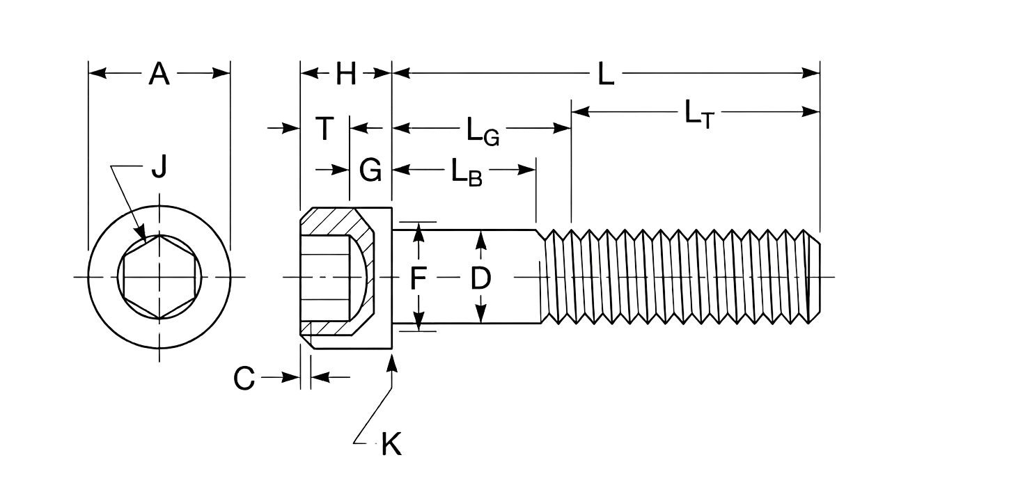
A – Head Diameter: The maximum width of the bolt head, which dictates the required size of a counterbore hole so the fastener can sit flush or recessed within a surface.
D – Body Diameter: The thickness of the unthreaded shank used to calculate the necessary clearance hole size and determine the bolt’s overall shear strength.
H – Head Height: The vertical thickness of the head, a critical measurement for ensuring the bolt does not protrude or interfere with other moving components in tight assemblies.
J – Hexagon Socket Size: The distance across the internal flats of the drive, which identifies the specific hex key or Allen wrench size needed for installation.
T – Socket Depth: The vertical engagement depth for the drive tool, ensuring there is enough surface area to transfer full torque without stripping the internal socket.
G – Minimum Wall Thickness: The metal remaining between the socket and the outer head edge, which provides the structural integrity needed to prevent the head from cracking under high tension.
L – Nominal Length: The total reach of the fastener from the under-head bearing surface to the tip, used as the primary identifier for ordering and specifying joint depth.
LG – Grip Length: The distance from the head to the first full thread, ensuring that the stronger, unthreaded portion of the bolt is positioned where the joined materials meet (the shear plane).
LB – Body Length: The unthreaded portion of the shank that provides a smooth, precise bearing surface for parts that must align or pivot without thread interference.
LT – Thread Length: The portion of the bolt featuring functional threads, which determines the maximum engagement depth into a tapped hole or nut to ensure a secure hold.
K – Edge of Head: The perimeter of the bolt head which determines the minimum clearance required within a counterbore and provides the structural boundary for the bearing surface.
F – Underhead Fillet: The curved radius where the shank meets the head, which provides essential stress relief to prevent the head from snapping off under heavy tension.
C – Top Head Chamfer: The beveled top edge of the head that removes sharp corners for user safety and helps guide tools into the socket more efficiently.
Technical Note
Grip Gaging Length (LG) = Lnom - LT(min)Calculated by subtracting the minimum thread length from the nominal length. It defines the maximum distance from the bearing surface to the first complete thread.
Body Length (LB) = LG - (5 x P)
Calculated by subtracting five thread pitches (P) from the Grip Gaging Length. This defines the minimum length of the perfectly smooth, unthreaded shank by accounting for thread runout.
LG & LB Calculation Example
Screw Size : 7/16-14 x 4.000 in.
Pitch (P) : 1 ÷ 14 TPI = 0.0714 in
LG : 4.000 - 1.380 = 2.620 in
LB : 2.620 - (5 x 0.0714) = 2.263 in
Length - Standard length and it's increments that are determined by the nominal screw size and length:
For nominal screw sizes 0 to 1.00 in :
0.13 through 0.25 in. lengths: 0.06 in. increments
0.25 through 1.00 in. lengths: 0.13 in. increments
1.00 through 3.50 in. lengths: 0.25 in. increments
3.50 through 7.00 in. lengths: 0.50 in. increments
7.00 through 10.00 in. lengths: 1.00 in. increments
For nominal screw sizes over 1.00 in.:
1.00 through 7.00 in. lengths: 0.50 in. increments
7.00 through 10.00 in. lengths: 1.00 in. increments
Over 10.00 in. lengths: 2.00 in. increments
Low-Cap Head Screw Dimensions
Screw Size
#4
#5
#6
#8
#10
1/4
5/16
3/8
7/16
1/2
5/8
D
Min
0.1075
0.1202
0.1329
0.1585
0.184
0.2435
0.3053
0.3678
0.4294
0.4919
0.6163
Max
0.112
0.125
0.138
0.164
0.19
0.25
0.3125
0.375
0.4375
0.5
0.625
A
Min
0.176
0.198
0.218
0.262
0.303
0.365
0.431
0.55
0.618
0.743
0.867
Max
0.183
0.205
0.226
0.27
0.312
0.375
0.437
0.562
0.625
0.75
0.875
H
Min
0.053
0.059
0.066
0.079
0.092
0.121
0.152
0.182
0.213
0.244
0.306
Max
0.059
0.065
0.072
0.085
0.098
0.127
0.158
0.192
0.223
0.254
0.316
C
Max
0.009
0.012
0.013
0.014
0.018
0.025
0.033
0.04
0.047
0.055
0.07
J
Decimal
0.05
0.062
0.062
0.078
0.094
0.125
0.156
0.188
0.219
0.25
0.312
Nominal
—
1/16
1/16
5/64
3/32
1/8
5/32
3/16
7/32
1/4
5/16
T
Min
0.038
0.044
0.05
0.06
0.072
0.094
0.11
0.115
0.135
0.151
0.25
K
Max
0.008
0.008
0.008
0.008
0.008
0.01
0.01
0.01
0.015
0.015
0.015
F
Min
0.117
0.132
0.144
0.172
0.202
0.261
0.329
0.397
0.465
0.531
0.664
Max
0.13
0.145
0.158
0.188
0.218
0.278
0.347
0.415
0.484
0.552
0.689
LT
Min
0.75
0.75
0.75
0.88
0.88
1
1.12
1.25
1.38
1.5
1.75
Max
0.99
1
1.05
1.19
1.27
1.5
1.71
1.94
2.17
2.38
2.82
Note: All measurements are in inches
Disclaimer: The dimensions presented on this page are based on the applicable industry standard. However, actual product measurements may vary slightly due to manufacturing practices, material selection, surface finish, and specified tolerance classes. Buyers and sourcing professionals are encouraged to verify final specifications with the manufacturer or supplier prior to procurement, particularly for critical applications.
Legend
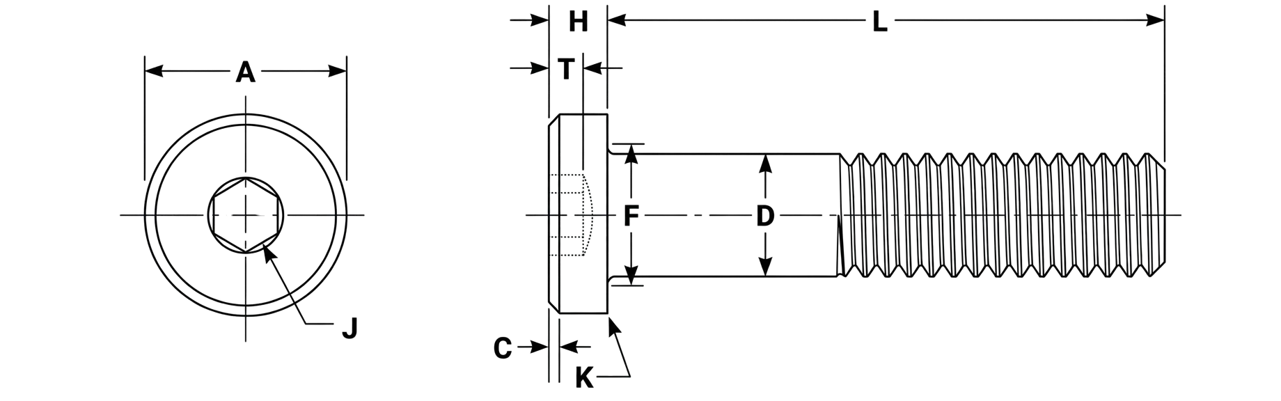
A – Head Diameter: The maximum width of the bolt head, which dictates the required size of a counterbore hole so the fastener can sit flush or recessed within a surface.
D – Body Diameter: The thickness of the unthreaded shank used to calculate the necessary clearance hole size and determine the bolt’s overall shear strength.
H – Head Height: The vertical thickness of the head, a critical measurement for ensuring the bolt does not protrude or interfere with other moving components in tight assemblies.
J – Hexagon Socket Size: The distance across the internal flats of the drive, which identifies the specific hex key or Allen wrench size needed for installation.
T – Socket Depth: The vertical engagement depth for the drive tool, ensuring there is enough surface area to transfer full torque without stripping the internal socket.
L – Nominal Length: The total reach of the fastener from the under-head bearing surface to the tip, used as the primary identifier for ordering and specifying joint depth.
K – Edge of Head: The perimeter of the bolt head which determines the minimum clearance required within a counterbore and provides the structural boundary for the bearing surface.
F – Underhead Fillet: The curved radius where the shank meets the head, which provides essential stress relief to prevent the head from snapping off under heavy tension.
C – Top Head Chamfer: The beveled top edge of the head that removes sharp corners for user safety and helps guide tools into the socket more efficiently.
Technical Note
Grip Gaging Length (LG) = Lnom - LT(min)Calculated by subtracting the minimum thread length from the nominal length. It defines the maximum distance from the bearing surface to the first complete thread.
Body Length (LB) = LG - (5 x P)
Calculated by subtracting five thread pitches (P) from the Grip Gaging Length. This defines the minimum length of the perfectly smooth, unthreaded shank by accounting for thread runout.
LG & LB Calculation Example
Screw Size : 7/16-14 x 4.000 in.
Pitch (P) : 1 ÷ 14 TPI = 0.0714 in
LG : 4.000 - 1.380 = 2.620 in
LB : 2.620 - (5 x 0.0714) = 2.263 in
Length - Standard length and it's increments that are determined by the nominal screw size and length:
For nominal screw sizes 0 to 1.00 in :
0.13 through 0.25 in. lengths: 0.06 in. increments
0.25 through 1.00 in. lengths: 0.13 in. increments
1.00 through 3.50 in. lengths: 0.25 in. increments
3.50 through 7.00 in. lengths: 0.50 in. increments
7.00 through 10.00 in. lengths: 1.00 in. increments
For nominal screw sizes over 1.00 in.:
1.00 through 7.00 in. lengths: 0.50 in. increments
7.00 through 10.00 in. lengths: 1.00 in. increments
Over 10.00 in. lengths: 2.00 in. increments
Flat Countersunk Head Screw Dimensions
Screw Size
#0
#1
#2
#3
#4
#5
#6
#8
#10
#12
1/4
5/16
3/8
7/16
1/2
5/8
3/4
7/8
1
1-1/8
1-1/4
1-3/8
1-1/2
D
Min
0.0568
0.0695
0.0822
0.0949
0.1075
0.1202
0.1329
0.1585
0.19
0.2158
0.25
0.3125
0.375
0.4294
0.4919
0.6163
0.7406
0.8647
0.9886
1.1086
1.2336
1.3568
1.4818
Max
0.06
0.073
0.086
0.099
0.112
0.125
0.138
0.164
0.19
0.2158
0.25
0.3125
0.375
0.4375
0.5
0.625
0.75
0.875
1
1.125
1.25
1.375
1.5
A
Min
0.117
0.143
0.168
0.193
0.218
0.24
0.263
0.311
0.359
0.41
0.48
0.6
0.72
0.781
0.872
1.112
1.355
1.604
1.841
2.079
2.316
2.553
2.791
Max
0.138
0.168
0.197
0.226
0.255
0.281
0.307
0.359
0.411
0.45
0.531
0.656
0.781
0.844
0.938
1.188
1.438
1.688
1.938
2.188
2.438
2.688
2.938
H
Reference
0.044
0.054
0.064
0.073
0.083
0.09
0.097
0.112
0.127
0.135
0.161
0.198
0.234
0.234
0.251
0.324
0.396
0.468
0.54
0.611
0.683
0.755
0.827
J
Decimal
0.035
0.05
0.05
0.062
0.062
0.078
0.078
0.094
0.125
0.125
0.156
0.188
0.219
0.25
0.312
0.375
0.5
0.562
0.625
0.75
0.875
0.875
1
Nominal
—
—
—
1/16
1/16
5/64
5/64
3/32
1/8
1/8
5/32
3/16
7/32
1/4
5/16
3/8
1/2
9/16
5/8
3/4
7/8
7/8
1
T
Min
0.025
0.031
0.038
0.044
0.055
0.061
0.066
0.076
0.087
0.094
0.111
0.135
0.159
0.159
0.172
0.22
0.22
0.248
0.297
0.325
0.358
0.402
0.435
F
Max
0.072
0.089
0.106
0.119
0.136
0.153
0.168
0.194
0.22
0.246
0.28
0.343
0.405
0.468
0.53
0.655
0.78
0.905
1.03
1.187
1.312
1.437
1.562
LT
Min
0.5
0.62
0.62
0.62
0.75
0.75
0.75
0.88
0.88
0.88
1
1.12
1.25
1.38
1.5
1.75
2
2.25
2.5
2.81
3.12
3.44
3.75
Max
0.62
0.77
0.8
0.83
0.99
1
1.05
1.19
1.27
1.27
1.5
1.71
1.94
2.17
2.38
2.82
3.25
3.69
4.12
4.65
5.09
5.65
6.08
Note: All measurements are in inches
Disclaimer: The dimensions presented on this page are based on the applicable industry standard. However, actual product measurements may vary slightly due to manufacturing practices, material selection, surface finish, and specified tolerance classes. Buyers and sourcing professionals are encouraged to verify final specifications with the manufacturer or supplier prior to procurement, particularly for critical applications.
Legend
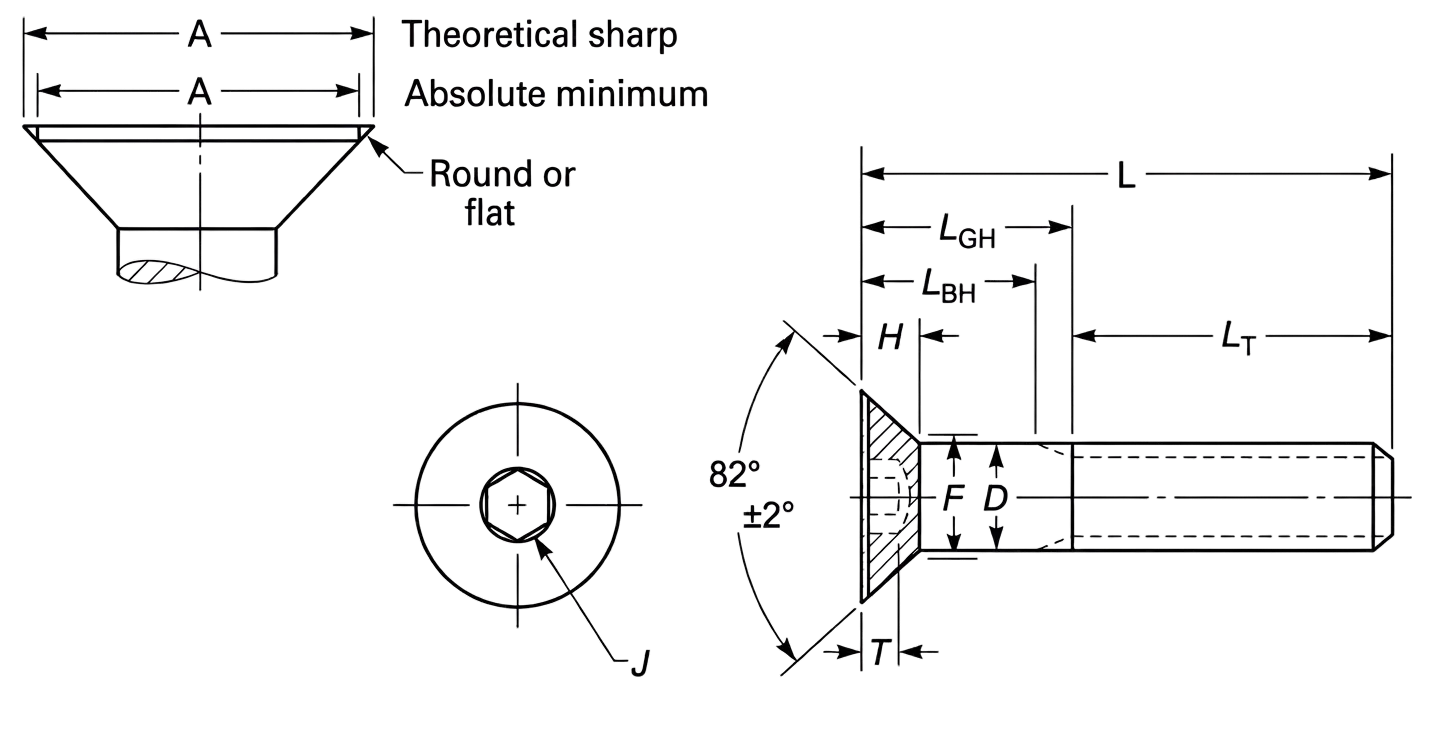
A – Head Diameter: The maximum width of the bolt head, which dictates the required size of a counterbore hole so the fastener can sit flush or recessed within a surface.
D – Body Diameter: The thickness of the unthreaded shank used to calculate the necessary clearance hole size and determine the bolt’s overall shear strength.
H – Head Height: The vertical thickness of the head, a critical measurement for ensuring the bolt does not protrude or interfere with other moving components in tight assemblies.
J – Hexagon Socket Size: The distance across the internal flats of the drive, which identifies the specific hex key or Allen wrench size needed for installation.
T – Socket Depth: The vertical engagement depth for the drive tool, ensuring there is enough surface area to transfer full torque without stripping the internal socket.
L – Nominal Length: The total reach of the fastener from the under-head bearing surface to the tip, used as the primary identifier for ordering and specifying joint depth.
LT – Thread Length: The portion of the bolt featuring functional threads, which determines the maximum engagement depth into a tapped hole or nut to ensure a secure hold.
F – Underhead Fillet: The curved radius where the shank meets the head, which provides essential stress relief to prevent the head from snapping off under heavy tension.
Technical Note
Grip Gaging Length (LG) = Lnom - LT(min)Calculated by subtracting the minimum thread length from the nominal length. It defines the maximum distance from the bearing surface to the first complete thread.
Body Length (LB) = LG - (5 x P)
Calculated by subtracting five thread pitches (P) from the Grip Gaging Length. This defines the minimum length of the perfectly smooth, unthreaded shank by accounting for thread runout.
LG & LB Calculation Example
Screw Size : 7/16-14 x 4.000 in.
Pitch (P) : 1 ÷ 14 TPI = 0.0714 in
LG : 4.000 - 1.380 = 2.620 in
LB : 2.620 - (5 x 0.0714) = 2.263 in
Length - Standard length and it's increments that are determined by the nominal screw size and length:
For nominal screw sizes 0 to 1.00 in :
0.13 through 0.25 in. lengths: 0.06 in. increments
0.25 through 1.00 in. lengths: 0.13 in. increments
1.00 through 3.50 in. lengths: 0.25 in. increments
3.50 through 7.00 in. lengths: 0.50 in. increments
7.00 through 10.00 in. lengths: 1.00 in. increments
For nominal screw sizes over 1.00 in.:
1.00 through 7.00 in. lengths: 0.50 in. increments
7.00 through 10.00 in. lengths: 1.00 in. increments
Over 10.00 in. lengths: 2.00 in. increments
Button Head Screw Dimensions
Screw Size
#0
#1
#2
#3
#4
#5
#6
#8
#10
1/4
5/16
3/8
7/16
1/2
5/8
3/4
A
Min
0.104
0.129
0.154
0.176
0.201
0.226
0.25
0.298
0.347
0.419
0.527
0.636
0.746
0.851
0.97
1.105
Max
0.114
0.139
0.164
0.188
0.213
0.238
0.262
0.312
0.361
0.437
0.547
0.656
0.765
0.875
1
1.125
H
Min
0.026
0.033
0.038
0.044
0.051
0.058
0.063
0.077
0.091
0.122
0.152
0.185
0.218
0.245
0.311
0.355
Max
0.032
0.039
0.046
0.052
0.059
0.066
0.073
0.087
0.101
0.132
0.166
0.199
0.231
0.265
0.331
0.375
S
Reference
0.01
0.01
0.01
0.01
0.015
0.015
0.015
0.015
0.02
0.031
0.031
0.031
0.031
0.046
0.062
0.062
J
Decimal
0.035
0.05
0.05
0.062
0.062
0.078
0.078
0.094
0.125
0.156
0.188
0.219
0.25
0.312
0.375
0.437
Nominal
—
—
—
1/16
1/16
5/64
5/64
3/32
1/8
5/32
3/16
7/32
1/4
5/16
3/8
7/16
T
Min
0.02
0.028
0.028
0.035
0.035
0.044
0.044
0.052
0.07
0.087
0.105
0.122
0.14
0.175
0.21
0.245
F
Min
0.07
0.083
0.096
0.109
0.122
0.135
0.148
0.184
0.21
0.28
0.343
0.405
0.468
0.54
0.665
0.72
Max
0.08
0.093
0.106
0.119
0.132
0.145
0.158
0.194
0.22
0.29
0.353
0.415
0.478
0.56
0.685
0.74
L
Nominal
0.5
0.5
0.5
0.5
0.5
0.5
0.63
0.75
1
1
1
1.25
1.5
2
2
2.5
Note: All measurements are in inches
Disclaimer: The dimensions presented on this page are based on the applicable industry standard. However, actual product measurements may vary slightly due to manufacturing practices, material selection, surface finish, and specified tolerance classes. Buyers and sourcing professionals are encouraged to verify final specifications with the manufacturer or supplier prior to procurement, particularly for critical applications.
Legend
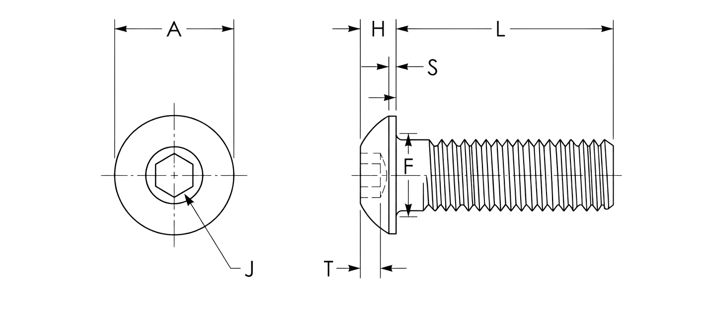
A – Head Diameter: The maximum width of the bolt head, which dictates the required size of a counterbore hole so the fastener can sit flush or recessed within a surface.
H – Head Height: The vertical thickness of the head, a critical measurement for ensuring the bolt does not protrude or interfere with other moving components in tight assemblies.
S – Head Side Height: The vertical height of the flat side profile of the head before it begins to curve, often relevant for clearance or aesthetic alignment.
J – Hexagon Socket Size: The distance across the internal flats of the drive, which identifies the specific hex key or Allen wrench size needed for installation.
T – Socket Depth: The vertical engagement depth for the drive tool, ensuring there is enough surface area to transfer full torque without stripping the internal socket.
L – Nominal Length: The total reach of the fastener from the under-head bearing surface to the tip, used as the primary identifier for ordering and specifying joint depth.
F – Underhead Fillet: The curved radius where the shank meets the head, which provides essential stress relief to prevent the head from snapping off under heavy tension.
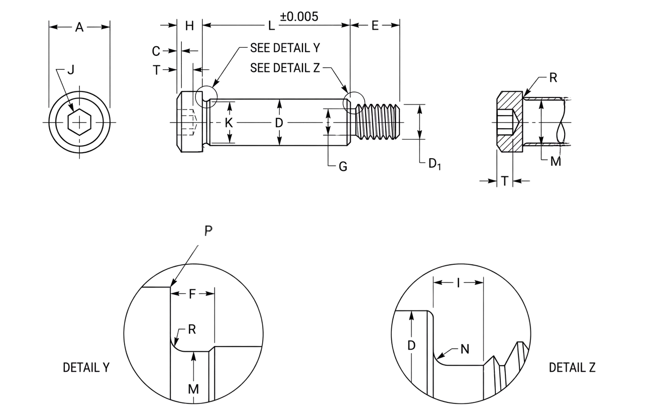
Shoulder Screw Dimensions
Screw Size
#4
#6
#8
#10
1/4
5/16
3/8
1/2
5/8
3/4
7/8
1-1/8
1-1/4
1-1/2
D
Min
0.121
0.152
0.183
0.246
0.3085
0.371
0.496
0.621
0.746
0.996
1.246
1.496
1.746
1.996
Max
0.123
0.154
0.185
0.248
0.3105
0.373
0.498
0.623
0.748
0.998
1.248
1.498
1.784
1.998
A
Min
0.235
0.266
0.296
0.357
0.419
0.543
0.729
0.853
0.977
1.287
1.723
2.095
2.345
2.72
Max
0.25
0.281
0.312
0.375
0.438
0.562
0.75
0.875
1
1.312
1.75
2.125
2.375
2.75
H
Min
0.115
0.115
0.146
0.177
0.209
0.24
0.302
0.365
0.49
0.61
0.735
0.98
1.105
1.23
Max
0.125
0.125
0.156
0.188
0.219
0.25
0.312
0.375
0.5
0.625
0.75
1
1.125
1.25
C
Max
0.008
0.008
0.012
0.02
0.026
0.031
0.04
0.05
0.069
0.083
0.102
0.138
0.157
0.176
J
Nominal
5/64
3/32
3/32
1/8
5/32
3/16
1/4
5/16
3/8
1/2
5/8
7/8
1
1-1/4
Decimal
0.078
0.094
0.094
0.125
0.156
0.188
0.25
0.312
0.375
0.5
0.625
0.875
1
1.25
T
Min
0.067
0.067
0.079
0.094
0.117
0.141
0.188
0.234
0.281
0.375
0.469
0.656
0.75
0.937
M
Max
0.138
0.172
0.207
0.276
0.345
0.413
0.55
0.687
0.826
1.098
1.368
1.638
1.908
2.178
R
Min
0.006
0.007
0.008
0.009
0.012
0.015
0.02
0.024
0.03
0.04
0.05
0.06
0.07
0.08
K
Min
0.108
0.14
0.154
0.227
0.289
0.352
0.477
0.602
0.727
0.977
1.227
1.478
1.728
1.978
F
Max
0.04
0.04
0.04
0.093
0.093
0.093
0.093
0.093
0.093
0.125
0.125
0.125
0.125
0.125
I
Max
0.078
0.063
0.069
0.083
0.1
0.111
0.125
0.154
0.182
0.2
0.222
0.286
0.286
0.333
N
Min
0.01
0.012
0.012
0.017
0.022
0.025
0.029
0.036
0.045
0.049
0.056
0.066
0.066
0.096
Max
0.016
0.018
0.018
0.023
0.008
0.031
0.035
0.042
0.051
0.055
0.062
0.072
0.072
0.102
P
Max
0.008
0.008
0.008
0.01
0.01
0.01
0.01
0.015
0.015
0.02
0.02
0.02
0.02
0.02
E
Nominal
0.157
0.187
0.189
0.375
0.438
0.5
0.625
0.75
0.875
1
1.125
1.5
1.75
2
Note: All measurements are in inches
Disclaimer: The dimensions presented on this page are based on the applicable industry standard. However, actual product measurements may vary slightly due to manufacturing practices, material selection, surface finish, and specified tolerance classes. Buyers and sourcing professionals are encouraged to verify final specifications with the manufacturer or supplier prior to procurement, particularly for critical applications.
Legend
A – Head Diameter: The outer width of the screw head, used to determine counterbore clearance.
H – Head Height: The vertical thickness of the head, critical for overhead clearance in tight assemblies.
C – Top Head Chamfer: The beveled top edge that removes sharp corners and helps guide the hex key into the socket.
J – Hexagon Socket Size: The distance across the internal flats, identifying the specific hex key or Allen wrench size needed.
T – Key Engagement: the depth of the internal socket to ensure full torque transfer without stripping.
R – Head Fillet Radius: The curved transition under the head that provides essential stress relief.
D – Shoulder Diameter: The precision-ground diameter of the unthreaded shank that serves as a bearing or pivot surface.
K – Shoulder Neck Diameter: The diameter of the undercut between the head and the shoulder.
F – Shoulder Neck Width: The width of the relief groove located directly under the screw head.
M – Fillet Transition Diameter: The specific diameter where the underhead fillet meets the shoulder or neck.
I – Thread Neck Width: The width of the relief groove between the shoulder and the threaded portion.
N – Thread Neck Fillet: The radius at the base of the thread neck to prevent stress concentrations.
E – Nominal Thread Length: The total reach of the threaded section from the shoulder base to the tip.
Technical Note
Measurement of Length - The length of the shoulder screw is measured parallel to the axis from the bearing surface plane under the head to the shoulder plane at the threaded end, expressed as a three-place decimal.
Standard Lengths - The difference between consecutive standard lengths is determined by the nominal screw length:
0.25 through 0.75 in. lengths: 0.13 in. increments
0.75 through 5.00 in. lengths: 0.25 in. increments