Unit Converter
ASME B18.5 – Dimensions Charts
ASME B18.5 is the American National Standard for Inch Series round head bolts. It provides complete general and dimensional data for various types of internally driven fasteners, including round head bolts (formerly button head), carriage bolts (square, short square, ribbed, and fin neck styles), step bolts, countersunk bolts, elevator bolts, and T-head bolts. Use the dimension charts below to find full specifications for head proportions, neck dimensions, thread lengths, and body diameters for every fastener category covered under the standard.
Dimensions & Size Chart


| Round Head Bolt Dimensions | |||||||||||
|---|---|---|---|---|---|---|---|---|---|---|---|
| Bolt Size | #10 | 1/4 | 5/16 | 3/8 | 7/16 | 1/2 | 5/8 | 3/4 | 7/8 | 1 | |
| E | Min | 0.182 | 0.237 | 0.298 | 0.36 | 0.421 | 0.483 | 0.605 | 0.729 | 0.852 | 0.976 |
| Max | 0.199 | 0.26 | 0.324 | 0.388 | 0.452 | 0.515 | 0.642 | 0.768 | 0.895 | 1.022 | |
| A | Min | 0.438 | 0.563 | 0.688 | 0.782 | 0.907 | 1.032 | 1.219 | 1.469 | 1.719 | 1.969 |
| Max | 0.469 | 0.594 | 0.719 | 0.844 | 0.969 | 1.094 | 1.344 | 1.594 | 1.844 | 2.094 | |
| H | Min | 0.094 | 0.125 | 0.156 | 0.188 | 0.219 | 0.25 | 0.313 | 0.375 | 0.438 | 0.5 |
| Max | 0.114 | 0.145 | 0.176 | 0.208 | 0.239 | 0.27 | 0.344 | 0.406 | 0.469 | 0.531 | |
| R | Max | 0.031 | 0.031 | 0.031 | 0.031 | 0.031 | 0.031 | 0.062 | 0.062 | 0.062 | 0.062 |
Note: All measurements are in inches
Disclaimer: The dimensions presented on this page are based on the applicable industry standard. However, actual product measurements may vary slightly due to manufacturing practices, material selection, surface finish, and specified tolerance classes. Buyers and sourcing professionals are encouraged to verify final specifications with the manufacturer or supplier prior to procurement, particularly for critical applications.
Legend
- E – Body Diameter: The thickness of the unthreaded shank used to calculate the necessary clearance hole size and determine the bolt’s overall shear strength.
- A – Head Diameter: The maximum width of the circular head, which determines the load-bearing surface area against the workpiece.
- H – Head Height: The vertical thickness from the bearing surface to the apex of the rounded head, critical for clearance in low-profile assemblies.
- R – Radius of Underhead Fillet: The curved transition where the shank meets the head; it provides essential stress relief to prevent the head from snapping under tension.
- LT – Thread Length: The portion of the bolt featuring functional threads, determining the maximum engagement depth into a tapped hole or nut.
- L – Nominal Length: The total reach of the fastener measured from the under-head bearing surface to the tip.
Technical Note
-
Length - Permissible tolerances based on nominal bolt size and length:
- Up to 1 in. lengths:
- Tolerance: +0.02 / -0.03 for sizes No. 10 through 3/4.
- Over 1 in. to 2-1/2 in. lengths:
- Tolerances range from +0.02 / -0.04 (No. 10–3/8") to +0.12 / -0.12 (1-1/8"–1-1/2").
- Over 2-1/2 in. to 4 in. lengths:
- Tolerances range from +0.04 / -0.06 (No. 10–3/8") to +0.16 / -0.16 (1-1/8"–1-1/2").
- Over 4 in. to 6 in. lengths:
- Tolerances range from +0.06 / -0.10 (No. 10–3/8") to +0.18 / -0.18 (1-1/8"–1-1/2").
- Over 6 in. lengths:
- Tolerances range from +0.10 / -0.18 (No. 10–3/8") to +0.22 / -0.22 (1-1/8"–1-1/2").
- Up to 1 in. lengths:
-
Thread Length Measurement
- The length of thread shall be measured parallel to the axis of the bolt.
- The measurement is taken from the end of the bolt to the last complete (full form) thread.
-
Thread Length Calculation and Constraints
- For nominal bolt lengths of 6 in. or shorter, the minimum thread length is equal to twice the basic bolt diameter plus 0.25 in.
- For longer nominal lengths, the minimum thread length is equal to twice the basic bolt diameter plus 0.50 in.
- Bolts with nominal lengths that are too short to accommodate these minimum thread lengths must be threaded for full length.
- The length from the head or neck to the first complete thread shall not exceed 2-1/2 threads for sizes up to and including 1 in.
- For sizes over 1 in., the length from the head or neck to the first complete thread shall not exceed 3-1/2 threads.
| Carriage Bolt Dimensions | |||||||||||
|---|---|---|---|---|---|---|---|---|---|---|---|
| Bolt Size | #10 | 1/4 | 5/16 | 3/8 | 7/16 | 1/2 | 5/8 | 3/4 | 7/8 | 1 | |
| E | Min | 0.159 | 0.213 | 0.272 | 0.329 | 0.385 | 0.444 | 0.559 | 0.678 | 0.795 | 0.91 |
| Max | 0.199 | 0.26 | 0.324 | 0.388 | 0.452 | 0.515 | 0.642 | 0.768 | 0.895 | 1.022 | |
| A | Min | 0.436 | 0.563 | 0.688 | 0.782 | 0.907 | 1.032 | 1.219 | 1.469 | 1.719 | 1.969 |
| Max | 0.469 | 0.594 | 0.719 | 0.844 | 0.969 | 1.094 | 1.344 | 1.594 | 1.844 | 2.094 | |
| H | Min | 0.094 | 0.125 | 0.156 | 0.188 | 0.219 | 0.25 | 0.313 | 0.375 | 0.438 | 0.5 |
| Max | 0.114 | 0.145 | 0.176 | 0.208 | 0.239 | 0.27 | 0.344 | 0.406 | 0.459 | 0.531 | |
| O | Min | 0.185 | 0.245 | 0.307 | 0.368 | 0.431 | 0.492 | 0.616 | 0.741 | 0.865 | 0.99 |
| Max | 0.199 | 0.26 | 0.324 | 0.388 | 0.452 | 0.515 | 0.642 | 0.768 | 0.895 | 1.022 | |
| P | Min | 0.094 | 0.125 | 0.156 | 0.188 | 0.219 | 0.25 | 0.313 | 0.375 | 0.438 | 0.5 |
| Max | 0.125 | 0.156 | 0.187 | 0.219 | 0.25 | 0.281 | 0.344 | 0.406 | 0.469 | 0.531 | |
| Q | Max | 0.031 | 0.031 | 0.031 | 0.047 | 0.047 | 0.047 | 0.078 | 0.078 | 0.094 | 0.094 |
| R | Max | 0.031 | 0.031 | 0.031 | 0.031 | 0.031 | 0.031 | 0.062 | 0.062 | 0.062 | 0.062 |
Note: All measurements are in inches
Disclaimer: The dimensions presented on this page are based on the applicable industry standard. However, actual product measurements may vary slightly due to manufacturing practices, material selection, surface finish, and specified tolerance classes. Buyers and sourcing professionals are encouraged to verify final specifications with the manufacturer or supplier prior to procurement, particularly for critical applications.
Legend
- E – Body Diameter: The thickness of the unthreaded shank used to calculate the necessary clearance hole size and determine the bolt’s overall shear strength.
- A – Head Diameter: The maximum width of the circular, low-profile head, which determines the load-bearing surface area against the workpiece.
- H – Head Height: The vertical thickness from the bearing surface to the apex of the rounded head.
- O – Square Width: The distance across the flats of the square neck, designed to lock into a matching square hole to prevent rotation.
- P – Square Depth: The vertical height of the square neck section below the head.
- Q – Corner Radius: The radius of the corners on the square neck, ensuring a proper fit within the pre-drilled square hole.
- R – Radius of Underhead Fillet: The curved transition where the shank meets the head; it provides essential stress relief to prevent the head from snapping under tension.
- LT – Thread Length: The portion of the bolt featuring functional threads, determining the maximum engagement depth into a tapped hole or nut.
- L – Nominal Length: The total reach of the fastener measured from the under-head bearing surface to the tip.
Technical Note
-
Length - Permissible tolerances based on nominal bolt size and length:
- Up to 1 in. lengths:
- Tolerance: +0.02 / -0.03 for sizes No. 10 through 3/4.
- Over 1 in. to 2-1/2 in. lengths:
- Tolerances range from +0.02 / -0.04 (No. 10–3/8") to +0.12 / -0.12 (1-1/8"–1-1/2").
- Over 2-1/2 in. to 4 in. lengths:
- Tolerances range from +0.04 / -0.06 (No. 10–3/8") to +0.16 / -0.16 (1-1/8"–1-1/2").
- Over 4 in. to 6 in. lengths:
- Tolerances range from +0.06 / -0.10 (No. 10–3/8") to +0.18 / -0.18 (1-1/8"–1-1/2").
- Over 6 in. lengths:
- Tolerances range from +0.10 / -0.18 (No. 10–3/8") to +0.22 / -0.22 (1-1/8"–1-1/2").
- Up to 1 in. lengths:
-
Thread Length Measurement
- The length of thread shall be measured parallel to the axis of the bolt.
- The measurement is taken from the end of the bolt to the last complete (full form) thread.
-
Thread Length Calculation and Constraints
- For nominal bolt lengths of 6 in. or shorter, the minimum thread length is equal to twice the basic bolt diameter plus 0.25 in.
- For longer nominal lengths, the minimum thread length is equal to twice the basic bolt diameter plus 0.50 in.
- Bolts with nominal lengths that are too short to accommodate these minimum thread lengths must be threaded for full length.
- The length from the head or neck to the first complete thread shall not exceed 2-1/2 threads for sizes up to and including 1 in.
- For sizes over 1 in., the length from the head or neck to the first complete thread shall not exceed 3-1/2 threads.
| Short Carriage Bolt Dimensions | ||||||||
|---|---|---|---|---|---|---|---|---|
| Bolt Size | 1/4 | 5/16 | 3/8 | 7/16 | 1/2 | 5/8 | 3/4 | |
| E | Min | 0.213 | 0.272 | 0.329 | 0.385 | 0.444 | 0.559 | 0.678 |
| Max | 0.26 | 0.324 | 0.388 | 0.452 | 0.515 | 0.642 | 0.768 | |
| A | Min | 0.563 | 0.688 | 0.782 | 0.907 | 1.032 | 1.219 | 1.469 |
| Max | 0.594 | 0.719 | 0.844 | 0.969 | 1.094 | 1.344 | 1.594 | |
| H | Min | 0.125 | 0.156 | 0.188 | 0.219 | 0.25 | 0.313 | 0.375 |
| Max | 0.145 | 0.176 | 0.208 | 0.239 | 0.27 | 0.344 | 0.406 | |
| O | Min | 0.245 | 0.307 | 0.368 | 0.431 | 0.492 | 0.616 | 0.741 |
| Max | 0.26 | 0.324 | 0.388 | 0.452 | 0.515 | 0.642 | 0.768 | |
| P | Min | 0.093 | 0.093 | 0.125 | 0.125 | 0.125 | 0.187 | 0.187 |
| Max | 0.124 | 0.124 | 0.156 | 0.156 | 0.156 | 0.218 | 0.218 | |
| Q | Max | 0.031 | 0.031 | 0.047 | 0.047 | 0.047 | 0.078 | 0.078 |
| R | Max | 0.031 | 0.031 | 0.031 | 0.031 | 0.031 | 0.062 | 0.062 |
Note: All measurements are in inches
Disclaimer: The dimensions presented on this page are based on the applicable industry standard. However, actual product measurements may vary slightly due to manufacturing practices, material selection, surface finish, and specified tolerance classes. Buyers and sourcing professionals are encouraged to verify final specifications with the manufacturer or supplier prior to procurement, particularly for critical applications.
Legend
- E – Body Diameter: The thickness of the unthreaded shank used to calculate the necessary clearance hole size and determine the bolt’s overall shear strength.
- A – Head Diameter: The maximum width of the circular, low-profile head, which determines the load-bearing surface area against the workpiece.
- H – Head Height: The vertical thickness from the bearing surface to the apex of the rounded head.
- O – Square Width: The distance across the flats of the square neck, designed to lock into a matching square hole to prevent rotation.
- P – Square Depth: The vertical height of the square neck section below the head.
- Q – Corner Radius: The radius of the corners on the square neck, ensuring a proper fit within the pre-drilled square hole.
- R – Radius of Underhead Fillet: The curved transition where the shank meets the head; it provides essential stress relief to prevent the head from snapping under tension.
- LT – Thread Length: The portion of the bolt featuring functional threads, determining the maximum engagement depth into a tapped hole or nut.
- L – Nominal Length: The total reach of the fastener measured from the under-head bearing surface to the tip.
Technical Note
-
Length - Permissible tolerances based on nominal bolt size and length:
- Up to 1 in. lengths:
- Tolerance: +0.02 / -0.03 for sizes No. 10 through 3/4.
- Over 1 in. to 2-1/2 in. lengths:
- Tolerances range from +0.02 / -0.04 (No. 10–3/8") to +0.12 / -0.12 (1-1/8"–1-1/2").
- Over 2-1/2 in. to 4 in. lengths:
- Tolerances range from +0.04 / -0.06 (No. 10–3/8") to +0.16 / -0.16 (1-1/8"–1-1/2").
- Over 4 in. to 6 in. lengths:
- Tolerances range from +0.06 / -0.10 (No. 10–3/8") to +0.18 / -0.18 (1-1/8"–1-1/2").
- Over 6 in. lengths:
- Tolerances range from +0.10 / -0.18 (No. 10–3/8") to +0.22 / -0.22 (1-1/8"–1-1/2").
- Up to 1 in. lengths:
-
Thread Length Measurement
- The length of thread shall be measured parallel to the axis of the bolt.
- The measurement is taken from the end of the bolt to the last complete (full form) thread.
-
Thread Length Calculation and Constraints
- For nominal bolt lengths of 6 in. or shorter, the minimum thread length is equal to twice the basic bolt diameter plus 0.25 in.
- For longer nominal lengths, the minimum thread length is equal to twice the basic bolt diameter plus 0.50 in.
- Bolts with nominal lengths that are too short to accommodate these minimum thread lengths must be threaded for full length.
- The length from the head or neck to the first complete thread shall not exceed 2-1/2 threads for sizes up to and including 1 in.
- For sizes over 1 in., the length from the head or neck to the first complete thread shall not exceed 3-1/2 threads.
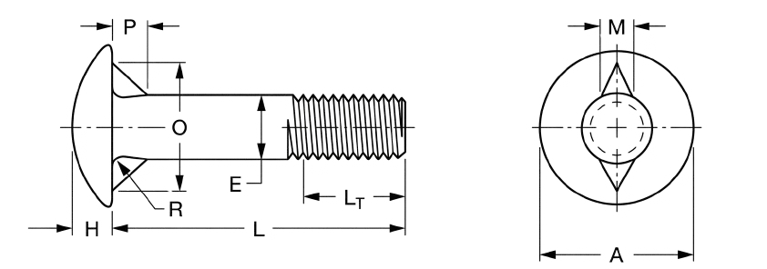
| Fin Bolt Dimensions | |||||||
|---|---|---|---|---|---|---|---|
| Bolt Size | #10 | 1/4 | 5/16 | 3/8 | 7/16 | 1/2 | |
| E | Min | 0.182 | 0.237 | 0.298 | 0.36 | 0.421 | 0.483 |
| Max | 0.199 | 0.26 | 0.324 | 0.388 | 0.452 | 0.515 | |
| A | Min | 0.438 | 0.563 | 0.688 | 0.782 | 0.907 | 1.032 |
| Max | 0.469 | 0.594 | 0.719 | 0.844 | 0.969 | 1.094 | |
| H | Min | 0.094 | 0.125 | 0.156 | 0.188 | 0.219 | 0.25 |
| Max | 0.114 | 0.145 | 0.176 | 0.208 | 0.239 | 0.27 | |
| O | Min | 0.375 | 0.438 | 0.531 | 0.625 | 0.719 | 0.813 |
| Max | 0.395 | 0.458 | 0.551 | 0.645 | 0.739 | 0.833 | |
| P | Min | 0.076 | 0.094 | 0.125 | 0.141 | 0.172 | 0.188 |
| Max | 0.088 | 0.104 | 0.135 | 0.151 | 0.182 | 0.198 | |
| Q | Max | — | — | — | — | — | — |
| R | Max | 0.031 | 0.031 | 0.031 | 0.031 | 0.031 | 0.031 |
Note: All measurements are in inches
Disclaimer: The dimensions presented on this page are based on the applicable industry standard. However, actual product measurements may vary slightly due to manufacturing practices, material selection, surface finish, and specified tolerance classes. Buyers and sourcing professionals are encouraged to verify final specifications with the manufacturer or supplier prior to procurement, particularly for critical applications.
Legend
- E – Body Diameter: The thickness of the unthreaded shank used to calculate the necessary clearance hole size and determine the bolt’s overall shear strength.
- A – Head Diameter: The maximum width of the circular, low-profile head, which determines the load-bearing surface area against the workpiece.
- H – Head Height: The vertical thickness from the bearing surface to the apex of the rounded head.
- M – Fin Thickness: The width of the individual fins located under the head, designed to bite into the material to prevent rotation.
- O – Distance Across Fins: The total measurement across the outer edges of the fins.
- P – Fin Depth: The vertical height or length of the fins extending down the shank from the underhead surface.
- R – Radius of Underhead Fillet: The curved transition where the shank meets the head; it provides essential stress relief to prevent the head from snapping under tension.
- LT – Thread Length: The portion of the bolt featuring functional threads, determining the maximum engagement depth into a tapped hole or nut.
- L – Nominal Length: The total reach of the fastener measured from the under-head bearing surface to the tip.
Technical Note
-
Length - Permissible tolerances based on nominal bolt size and length:
- Up to 1 in. lengths:
- Tolerance: +0.02 / -0.03 for sizes No. 10 through 3/4.
- Over 1 in. to 2-1/2 in. lengths:
- Tolerances range from +0.02 / -0.04 (No. 10–3/8") to +0.12 / -0.12 (1-1/8"–1-1/2").
- Over 2-1/2 in. to 4 in. lengths:
- Tolerances range from +0.04 / -0.06 (No. 10–3/8") to +0.16 / -0.16 (1-1/8"–1-1/2").
- Over 4 in. to 6 in. lengths:
- Tolerances range from +0.06 / -0.10 (No. 10–3/8") to +0.18 / -0.18 (1-1/8"–1-1/2").
- Over 6 in. lengths:
- Tolerances range from +0.10 / -0.18 (No. 10–3/8") to +0.22 / -0.22 (1-1/8"–1-1/2").
- Up to 1 in. lengths:
-
Thread Length Measurement
- The length of thread shall be measured parallel to the axis of the bolt.
- The measurement is taken from the end of the bolt to the last complete (full form) thread.
-
Thread Length Calculation and Constraints
- For nominal bolt lengths of 6 in. or shorter, the minimum thread length is equal to twice the basic bolt diameter plus 0.25 in.
- For longer nominal lengths, the minimum thread length is equal to twice the basic bolt diameter plus 0.50 in.
- Bolts with nominal lengths that are too short to accommodate these minimum thread lengths must be threaded for full length.
- The length from the head or neck to the first complete thread shall not exceed 2-1/2 threads for sizes up to and including 1 in.
- For sizes over 1 in., the length from the head or neck to the first complete thread shall not exceed 3-1/2 threads.
| Step Bolt Dimensions | |||||||
|---|---|---|---|---|---|---|---|
| Bolt Size | #10 | 1/4 | 5/16 | 3/8 | 7/16 | 1/2 | |
| E | Min | 0.182 | 0.237 | 0.298 | 0.36 | 0.421 | 0.483 |
| Max | 0.199 | 0.26 | 0.324 | 0.388 | 0.452 | 0.515 | |
| A | Min | 0.625 | 0.813 | 1 | 1.188 | 1.375 | 1.563 |
| Max | 0.656 | 0.844 | 1.031 | 1.219 | 1.406 | 1.594 | |
| H | Min | 0.094 | 0.125 | 0.156 | 0.188 | 0.219 | 0.25 |
| Max | 0.114 | 0.145 | 0.176 | 0.208 | 0.239 | 0.27 | |
| O | Min | 0.185 | 0.245 | 0.307 | 0.368 | 0.431 | 0.492 |
| Max | 0.199 | 0.26 | 0.324 | 0.388 | 0.452 | 0.515 | |
| P | Min | 0.094 | 0.125 | 0.156 | 0.188 | 0.219 | 0.25 |
| Max | 0.125 | 0.156 | 0.187 | 0.219 | 0.25 | 0.281 | |
| Q | Max | 0.031 | 0.031 | 0.031 | 0.047 | 0.047 | 0.047 |
| R | Max | 0.031 | 0.031 | 0.031 | 0.031 | 0.031 | 0.031 |
Note: All measurements are in inches
Disclaimer: The dimensions presented on this page are based on the applicable industry standard. However, actual product measurements may vary slightly due to manufacturing practices, material selection, surface finish, and specified tolerance classes. Buyers and sourcing professionals are encouraged to verify final specifications with the manufacturer or supplier prior to procurement, particularly for critical applications.
Legend
- E – Body Diameter: The thickness of the unthreaded shank used to calculate the necessary clearance hole size and determine the bolt’s overall shear strength.
- A – Head Diameter: The maximum width of the large, flat countersunk head, designed to provide a flush surface and high pull-through resistance.
- H – Head Height: The vertical thickness of the head at its thickest point.
- C – Head Angle: The inclusive angle of the countersink on the underside of the head.
- F – Flat Edges: The width of the flat outer edge or rim of the head diameter.
- O – Square Width: The distance across the flats of the square neck, designed to lock into the material and prevent rotation during tightening.
- P – Square Depth: The vertical height of the square neck section located immediately below the head.
- R – Radius of Underhead Fillet: The curved transition where the shank meets the square neck or head; it provides essential stress relief.
- LT – Thread Length: The portion of the bolt featuring functional threads, determining the maximum engagement depth into a tapped hole or nut.
- L – Nominal Length: The total reach of the fastener measured from the top of the head to the tip.
Technical Note
-
Length - Permissible tolerances based on nominal bolt size and length:
- Up to 1 in. lengths:
- Tolerance: +0.02 / -0.03 for sizes No. 10 through 3/4.
- Over 1 in. to 2-1/2 in. lengths:
- Tolerances range from +0.02 / -0.04 (No. 10–3/8") to +0.12 / -0.12 (1-1/8"–1-1/2").
- Over 2-1/2 in. to 4 in. lengths:
- Tolerances range from +0.04 / -0.06 (No. 10–3/8") to +0.16 / -0.16 (1-1/8"–1-1/2").
- Over 4 in. to 6 in. lengths:
- Tolerances range from +0.06 / -0.10 (No. 10–3/8") to +0.18 / -0.18 (1-1/8"–1-1/2").
- Over 6 in. lengths:
- Tolerances range from +0.10 / -0.18 (No. 10–3/8") to +0.22 / -0.22 (1-1/8"–1-1/2").
- Up to 1 in. lengths:
-
Thread Length Measurement
- The length of thread shall be measured parallel to the axis of the bolt.
- The measurement is taken from the end of the bolt to the last complete (full form) thread.
-
Thread Length Calculation and Constraints
- For nominal bolt lengths of 6 in. or shorter, the minimum thread length is equal to twice the basic bolt diameter plus 0.25 in.
- For longer nominal lengths, the minimum thread length is equal to twice the basic bolt diameter plus 0.50 in.
- Bolts with nominal lengths that are too short to accommodate these minimum thread lengths must be threaded for full length.
- The length from the head or neck to the first complete thread shall not exceed 2-1/2 threads for sizes up to and including 1 in.
- For sizes over 1 in., the length from the head or neck to the first complete thread shall not exceed 3-1/2 threads.
| Elevator Bolt Dimensions | |||||||
|---|---|---|---|---|---|---|---|
| Bolt Size | #10 | 1/4 | 5/16 | 3/8 | 7/16 | 1/2 | |
| E | Min | 0.182 | 0.237 | 0.298 | 0.36 | 0.421 | 0.483 |
| Max | 0.199 | 0.26 | 0.324 | 0.388 | 0.452 | 0.515 | |
| A | Min | 0.74 | 0.938 | 1.157 | 1.272 | 1.397 | 1.522 |
| Max | 0.79 | 1.008 | 1.227 | 1.352 | 1.477 | 1.602 | |
| C | Reference | 9 | 9 | 9 | 11 | 13 | 12 |
| F | Max | 0.025 | 0.035 | 0.035 | 0.04 | 0.04 | 0.04 |
| H | Min | 0.062 | 0.078 | 0.094 | 0.125 | 0.156 | 0.156 |
| Max | 0.082 | 0.098 | 0.114 | 0.145 | 0.176 | 0.176 | |
| O | Min | 0.185 | 0.245 | 0.307 | 0.368 | 0.431 | 0.492 |
| Max | 0.21 | 0.28 | 0.342 | 0.405 | 0.468 | 0.53 | |
| P | Min | 0.094 | 0.188 | 0.219 | 0.219 | 0.25 | 0.25 |
| Max | 0.125 | 0.219 | 0.25 | 0.25 | 0.281 | 0.281 | |
| Q | Max | 0.031 | 0.031 | 0.031 | 0.047 | 0.047 | 0.047 |
| R | Max | 0.031 | 0.031 | 0.031 | 0.031 | 0.031 | 0.031 |
Note: All measurements are in inches
Disclaimer: The dimensions presented on this page are based on the applicable industry standard. However, actual product measurements may vary slightly due to manufacturing practices, material selection, surface finish, and specified tolerance classes. Buyers and sourcing professionals are encouraged to verify final specifications with the manufacturer or supplier prior to procurement, particularly for critical applications.
Legend
- E – Body Diameter: The thickness of the unthreaded shank used to calculate the necessary clearance hole size and determine the bolt’s overall shear strength.
- F – Width Across Flats: The distance between two parallel flat surfaces of the bolt head, used to identify the correct wrench or spanner size for installation.
- G – Width Across Corners: The maximum diameter of the hexagonal head measured from point to point, ensuring enough clearance for the tool to rotate.
- H – Head Height: The vertical thickness of the head, critical for ensuring the bolt does not protrude or interfere with moving components in tight assemblies.
- R – Radius of Underhead Fillet: The curved transition where the shank meets the head; it provides essential stress relief to prevent the head from snapping under tension.
- LT – Thread Length: The portion of the bolt featuring functional threads, determining the maximum engagement depth into a tapped hole or nut.
- L – Nominal Length: The total reach of the fastener from the under-head bearing surface to the tip.
- LG – Grip Length: The distance from the head to the first full thread (the unthreaded shear plane).
Technical Note
-
Length - Permissible tolerances based on nominal bolt size and length:
- Up to 1 in. lengths:
- Tolerance: +0.02 / -0.03 for sizes No. 10 through 3/4.
- Over 1 in. to 2-1/2 in. lengths:
- Tolerances range from +0.02 / -0.04 (No. 10–3/8") to +0.12 / -0.12 (1-1/8"–1-1/2").
- Over 2-1/2 in. to 4 in. lengths:
- Tolerances range from +0.04 / -0.06 (No. 10–3/8") to +0.16 / -0.16 (1-1/8"–1-1/2").
- Over 4 in. to 6 in. lengths:
- Tolerances range from +0.06 / -0.10 (No. 10–3/8") to +0.18 / -0.18 (1-1/8"–1-1/2").
- Over 6 in. lengths:
- Tolerances range from +0.10 / -0.18 (No. 10–3/8") to +0.22 / -0.22 (1-1/8"–1-1/2").
- Up to 1 in. lengths:
-
Thread Length Measurement
- The length of thread shall be measured parallel to the axis of the bolt.
- The measurement is taken from the end of the bolt to the last complete (full form) thread.
-
Thread Length Calculation and Constraints
- For nominal bolt lengths of 6 in. or shorter, the minimum thread length is equal to twice the basic bolt diameter plus 0.25 in.
- For longer nominal lengths, the minimum thread length is equal to twice the basic bolt diameter plus 0.50 in.
- Bolts with nominal lengths that are too short to accommodate these minimum thread lengths must be threaded for full length.
- The length from the head or neck to the first complete thread shall not exceed 2-1/2 threads for sizes up to and including 1 in.
- For sizes over 1 in., the length from the head or neck to the first complete thread shall not exceed 3-1/2 threads.
| T Bolt Dimensions | ||||||||||
|---|---|---|---|---|---|---|---|---|---|---|
| Bolt Size | 1/4 | 5/16 | 3/8 | 7/16 | 1/2 | 5/8 | 3/4 | 7/8 | 1 | |
| E | Min | 0.237 | 0.298 | 0.36 | 0.421 | 0.483 | 0.605 | 0.729 | 0.852 | 0.976 |
| Max | 0.26 | 0.324 | 0.388 | 0.452 | 0.515 | 0.642 | 0.768 | 0.895 | 1.022 | |
| A | Min | 0.488 | 0.609 | 0.731 | 0.853 | 0.975 | 1.218 | 1.462 | 1.706 | 1.95 |
| Max | 0.5 | 0.625 | 0.75 | 0.875 | 1 | 1.25 | 1.5 | 1.75 | 2 | |
| B | Min | 0.245 | 0.307 | 0.368 | 0.431 | 0.492 | 0.616 | 0.741 | 0.865 | 0.99 |
| Max | 0.28 | 0.342 | 0.405 | 0.468 | 0.53 | 0.675 | 0.8 | 0.938 | 1.063 | |
| H | Min | 0.172 | 0.233 | 0.295 | 0.356 | 0.418 | 0.541 | 0.601 | 0.724 | 0.847 |
| Max | 0.204 | 0.267 | 0.331 | 0.394 | 0.458 | 0.585 | 0.649 | 0.776 | 0.903 | |
| K | Nominal | 0.438 | 0.5 | 0.625 | 0.875 | 0.875 | 1.062 | 1.25 | 1.375 | 1.5 |
| R | Max | 0.031 | 0.031 | 0.031 | 0.031 | 0.031 | 0.062 | 0.062 | 0.062 | 0.062 |
Note: All measurements are in inches
Disclaimer: The dimensions presented on this page are based on the applicable industry standard. However, actual product measurements may vary slightly due to manufacturing practices, material selection, surface finish, and specified tolerance classes. Buyers and sourcing professionals are encouraged to verify final specifications with the manufacturer or supplier prior to procurement, particularly for critical applications.
Legend
- E – Body Diameter: The thickness of the unthreaded shank used to calculate the necessary clearance hole size and determine the bolt’s overall shear strength.
- A – Head Length: The total length of the rectangular T-shaped head, designed to span the width of a T-slot.
- B – Head Width: The width of the T-head, which must be narrow enough to slide into the slot but wide enough to provide a secure bearing surface.
- H – Head Height: The vertical thickness of the T-head from the bearing surface to the top of the bolt.
- K – Head Radius: The radius applied to the corners or transitions of the T-head to ensure smooth movement within the track.
- R – Radius of Underhead Fillet: The curved transition where the shank meets the head; it provides essential stress relief to prevent the head from snapping under tension.
- LT – Thread Length: The portion of the bolt featuring functional threads, determining the maximum engagement depth into a nut or fixture.
- L – Nominal Length: The total reach of the fastener measured from the under-head bearing surface to the tip.
Technical Note
-
Length - Permissible tolerances based on nominal bolt size and length:
- Up to 1 in. lengths:
- Tolerance: +0.02 / -0.03 for sizes No. 10 through 3/4.
- Over 1 in. to 2-1/2 in. lengths:
- Tolerances range from +0.02 / -0.04 (No. 10–3/8") to +0.12 / -0.12 (1-1/8"–1-1/2").
- Over 2-1/2 in. to 4 in. lengths:
- Tolerances range from +0.04 / -0.06 (No. 10–3/8") to +0.16 / -0.16 (1-1/8"–1-1/2").
- Over 4 in. to 6 in. lengths:
- Tolerances range from +0.06 / -0.10 (No. 10–3/8") to +0.18 / -0.18 (1-1/8"–1-1/2").
- Over 6 in. lengths:
- Tolerances range from +0.10 / -0.18 (No. 10–3/8") to +0.22 / -0.22 (1-1/8"–1-1/2").
- Up to 1 in. lengths:
-
Thread Length Measurement
- The length of thread shall be measured parallel to the axis of the bolt.
- The measurement is taken from the end of the bolt to the last complete (full form) thread.
-
Thread Length Calculation and Constraints
- For nominal bolt lengths of 6 in. or shorter, the minimum thread length is equal to twice the basic bolt diameter plus 0.25 in.
- For longer nominal lengths, the minimum thread length is equal to twice the basic bolt diameter plus 0.50 in.
- Bolts with nominal lengths that are too short to accommodate these minimum thread lengths must be threaded for full length.
- The length from the head or neck to the first complete thread shall not exceed 2-1/2 threads for sizes up to and including 1 in.
- For sizes over 1 in., the length from the head or neck to the first complete thread shall not exceed 3-1/2 threads.